

Custom Search
|
|

|
||
 MIL-HDBK-419A
In a manner analogous to the classical equations (8-1) describing reflections in transmission lines, the
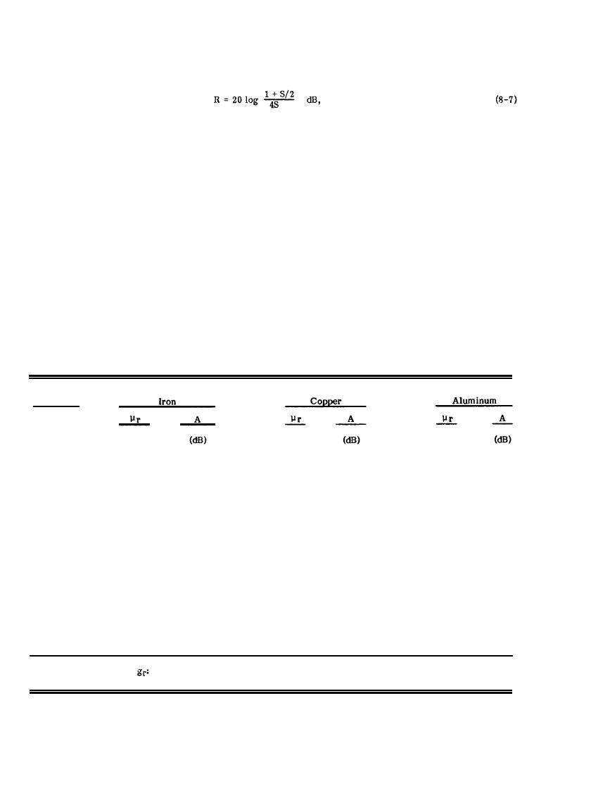
shield reflection loss can be expressed as:
where S is defined as the ratio of the wave impedance to the shield's intrinsic impedance and is analogous to the
voltage standing wave ratio in transmission line practice. While the shield's intrinsic impedance is easily
determined from the electrical properties of the shield material, the wave impedance is highly dependent upon
the type and location of the EM wave source, as indicated in Figure 8-4.
In order to present practical methods for determination of the reflection loss, three separate classes of EM
waves are considered and approximations for the reflection loss relationships applicable to the three classes are
presented. Since wave impedance is the ratio of electric to magnetic field strengths, a predominantly magnetic
field will have a low impedance and a predominantly electric field will have a high impedance. The three wave
impedance classes to be considered are low, medium, and high and are commonly referred to as the magnetic,
plane wave, and electric field, respectively.
Table 8-2
Absorption Loss, A, of 1 mm Metal Sheet (8-2)
1
0.8
1
60.0 Hz
1,000
1
13
1
4
1
3.0
1.0 kHz
1,000
54
1
10.0
10.0 kHz
1,000
171
1
13
1
40.0
150.0 kHz
663
1
56
1,000
1
103.0
1
131
1.0 MHz
700
1,430
1
178.0
3.0 MHz
600
2,300
1
228
1
325.0
10.0 MHz
500
3,830
1
416
1
509
1
397.0
15.0 MHz
400
4,200
1
1,030.0
100.0 MHz
100
5,420
1
1,310
1.0 GHz
50
12,110
1
4,160
1
3,250.0
1.5 GHz
10
6,640
5,090
1
3,970.0
10.0 GHz
1
10,300.0
1
5,420
1
13,140
Relative Conductivity,
Iron - 0.17, Copper - 1.0, Aluminum - 0.61.
8-8
|
 |
|
|
||


