
Custom Search
|
|

|
||
 MIL-HDBK-419A
=
r
distance from EM source to shield,
=
f
frequency (Hz),
conductivity of shield material relative to copper,
relative permeability of shield material,
and the constants
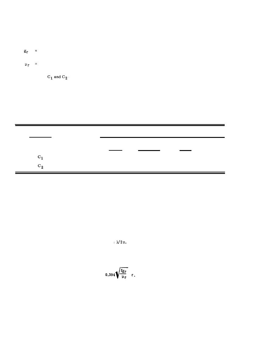
depend upon the choice of units for the distance, r, as given in Table 8-3.
Table 8-3
Coefficients for Magnetic Field Reflection Loss
Coefficient
Units for Distance (r)
Meters
Millimeters
Mils
Inches
462
0.462
.0117
11.7
136
.0053
0.136
5.35
As with absorption loss, the reflection loss for low impedance fields depends upon electrical properties of the
shield material and upon the EM wave frequency. However, the reflection loss depends upon the distance from
the source to the shield rather than upon the shield thickness.
Figure 8-5 shows the reflection loss as a function of frequency for iron, copper, and aluminum shields at
distances of one inch (2.54 cm) and ten inches (25.4 cm) from the low impedance EM field source. For a given
separation distance, the reflection loss is seen to be greater for copper and aluminum than for iron except at
the lower frequencies where iron has a better reflection loss. The curves cannot be extended to higher
frequencies for these separation distances since the approximations used in the derivation of Equation 8-8
assume that the separation distance, r, is less than
For higher frequencies at these distances, the EM
fields are more closely approximated by plane waves rather than by low impedance fields. Figure 8-6 is a
universal curve of the reflection loss for low-impedance sources as a function of the parameter
8-11
|
 |
|
 |
||