

Custom Search
|
|

|
||
 MIL-HDBK-419A
8.3.3 Re-Reflection Correction Factor.
For shields in which the absorption loss (A) is reasonably large, say at least 10 dB, the energy reflected back
into the shield at the second surface does not contribute significantly to the wave propagated through and
beyond the shield. However, when the shield's absorption loss is low, a significant amount of energy is reflected
at the second surface and finally propagated into the area to be shielded. Accordingly, for shields with low
absorption, the shielding effectiveness is calculated as the sum of (1) the absorption loss, A, (2) the reflection
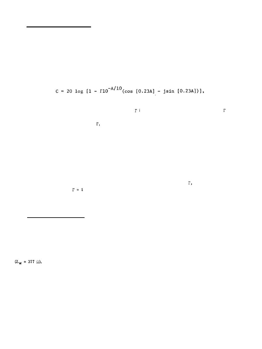
loss, R, and (3) a re-reflection correction factor, C. The correction factor is
(8-11)
where A is the shield's absorption loss (see Equation 8-5) and
is the two-boundary reflection coefficient;
is
dependent upon both the shield characteristic impedance and the wave impedance of the impinging EM wave.
Equations for the reflection coefficient,
are given in terms of a precalculation parameter, m, for each of
three wave impedance classes in Table 8-5.
Values of the re-reflection correction terms for iron and copper sheets of various thicknesses and typical
frequencies are given in Table 8-6. The correction term is seen to approach zero for thick shields or high
frequencies since these conditions correspond to large absorption losses in the shield. The larger absorption loss
of iron (compared with copper) for fixed frequency and thickness is also seen to result in a smaller correction
term. Figure 8-11 presents the correction term in graphical form for copper in a magnetic (low impedance)
field. Figure 8-12 presents a universal absorption loss curve (Equation 8-5). Recall that the correction term
(Equation 8-11) depends upon the absorption loss, A, and that the reflection coefficient,
is essentially unity.
Whenever the approximation
is valid, the correction term depends only upon the value of the absorption
loss. For such conditions, the sum of the absorption loss and the re-reflection correction term is given by the
dashed line on the universal curve in Figure 8-12.
8.3.4 Total Shielding Effectiveness. The item of interest for any shield is the (total) shielding effectiveness,
i.e., the sum of the absorption loss (A), reflection loss (R), and the multi-reflection correction term (C). The
terms, A, R, and C are of significance only as a means of predicting the shielding effectiveness. Table 8-7
contains the individual terms and the total shielding effectiveness for various shield thicknesses and EM wave
frequencies for copper, iron, and aluminum shields. The entries under "SOURCE" designate the EM wave
impedance classification: L indicates a loop antenna and designates a predominantly magnetic field, D
indicates an electric dipole antenna and designates a predominantly electric field, and P indicates a plane wave
All entries except the plane waves are for a source-to-shield separation distance of one foot.
Figures 8-13 and 8-14 illustrate the total theoretical shielding performance which one may expect to obtain
from enclosures constructed from copper foil and iron sheet to the electric, magnetic and plane wave
propagation modes, although the effect of doors, ventilation apertures, and power line penetrations has not been
considered, in many applications these penetrations, together with techniques used for joining the shield
materials, markedly reduce the overall practical insertion loss of a shielded enclosure.
8-19
|
 |
|
|
||


