
Custom Search
|
|

|
||
 MIL-HDBK-419A
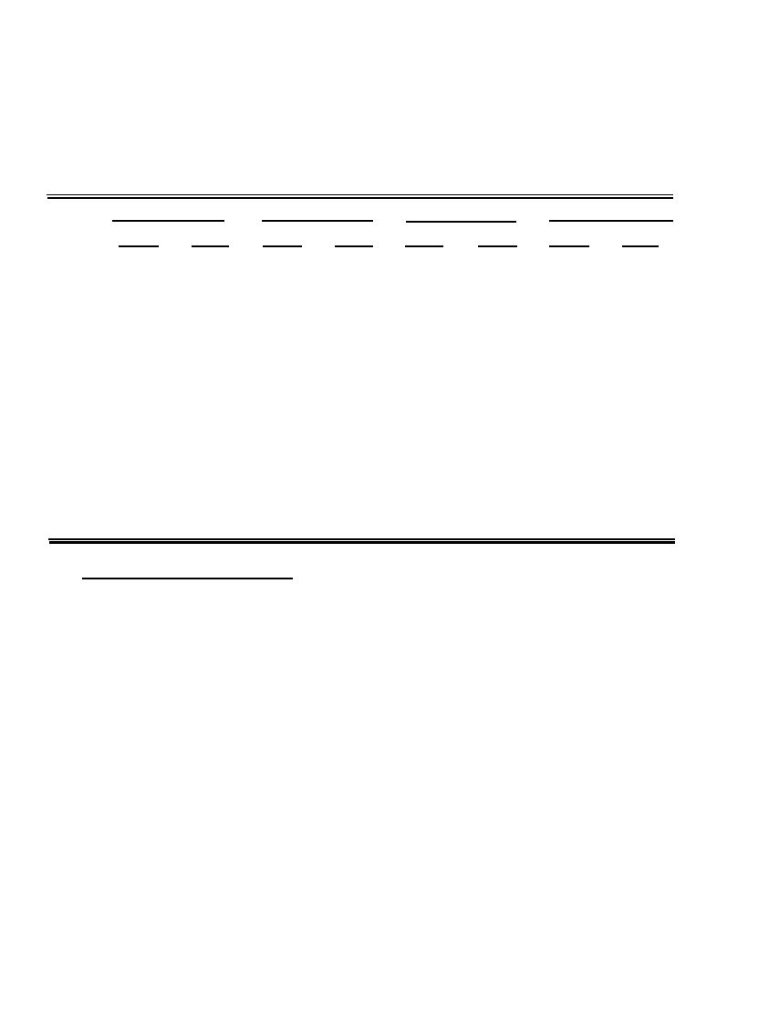
Table 8-11 provides representative calculations of the shielding effectiveness of thin-film cover for different
thicknesses and frequencies. One-quarter wavelength in copper is approximately 0.13 mils at 1 GHz, and it can
be seen that shield effectiveness changes significantly above this thickness.
Table 8-11
Calculated Values of Copper Thin-Film Shielding Effectiveness in dB Against Plane-Wave Energy (8-7)
0.0041 M i l s
0.86 Mils
Thickness
0.086 M i l s
0.049 M i l s
1 GHz
1 MHz
1 GHz
1 GHz
1 MHz
1 MHz
1 GHz
1 MHz
Absorption
92
0.014
0.44
9.2
2.9
5.2
0.29
Loss, A
0.16
Single
109
79
109
79
79
109
79
Loss, R
109
Multiple
Correction
-47
-17
-26
-6
-21
0.6
-3.5
Term, C
Shield
Effectiveness,
62
62
83
78
90
108
171
SE
88
8.4.3 Screens and Perforated Metal Shields.
There are many applications in which the shield cannot be made of a solid material. Screens and perforated
materials must be employed if an enclosure must be transparent (e.g., a meter face) or ventilated. The
shielding effectiveness of solid metal shields has been treated from the viewpoint of classical transmission line
theory in the preceding sections. To obtain an expression for shielding effectiveness which is applicable to
screens and perforated metal sheets, it is necessary to account for the following:
a.
The attenuation effects of the individual shield apertures
acting as
many
stacked
waveguides-below-cutoff (see Section 8.5.3.1).
b.
Reflection losses, considering the geometry of the openings.
c.
Area of the opening when the test antenna is far from the shield in comparison to the distance
between holes in the shield.
d.
Skin depth effects.
e.
Coupling between closely spaced openings.
8-33
|
 |
|
 |
||