

Custom Search
|
|

|
||
 MIL-HDBK-419A
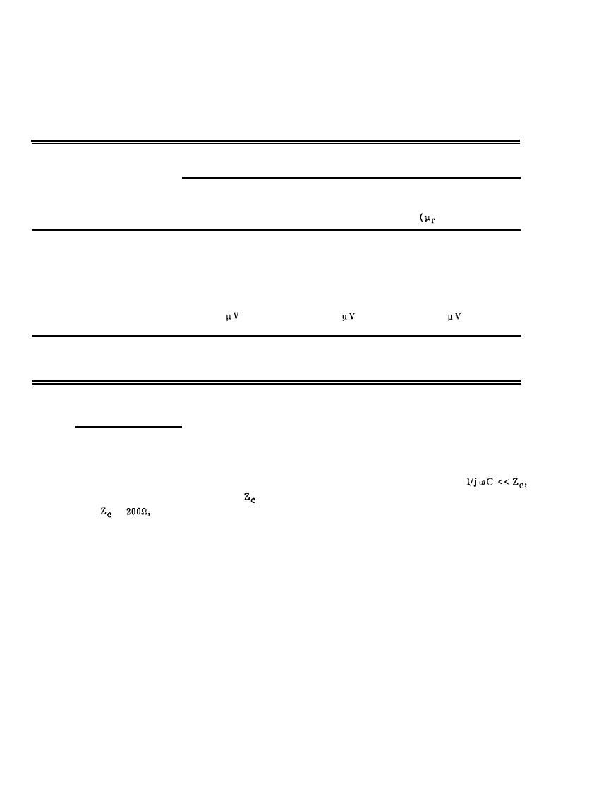
Table 10-1
Shielding by Diffusion
Internal Voltage Induced in Loop *
Shield
Thickness
Copper
Aluminum
Steel
5.8 x 10⁷ S/m
6 x 10⁶ S/m
3.7 x 10⁷ S/m
(mm)
= 200)
0.2
0.34 V
0.85 V
0.076 V
1.0
2.6 mV
6.4 mV
1.1 mV
5.0
21.0
51.0
15.0
*Peak voltage induced in a loop by radius 10 m inside a spherical shield or radius 10 m illuminated by a
high-altitude EMP (by diffusion through walls only).
10.3.2.2 Penetrating Conductors.
Conductors, such as power and signal wires, that pass through the shield, as
illustrated in Figure 10-7, may allow very large currents and voltages to be delivered to internal circuits. The
current on the wire just inside the shield is about equal to the current just outside the shield; the wire is a 0 dB
compromise of the shield. (At high frequencies, the capacitance between the wire and the shield wall may
cause some attenuation of the wire current, but this effect is negligible at frequencies such that
where C is the wire-to-shield capacitance and
is the load impedance on the wire. (For nominal values of
C = 10 pF and
=
f = 80 MHz for a 6-dB loss.) Thus a major concern for HEMP interaction is the
penetrating conductor that can guide HEMP-induced waves through shield walls. As discussed above and
illustrated in Figure 10-7, the shield is effective in excluding the incident electromagnetic waves, but it has
little effect on the waves guided through it on insulated penetrating conductors (10-8).
10-10
|
 |
|
|
||


