
Custom Search
|
|

|
||
 MIL-HDBK-419A
10.4.2.4 Waveguide Penetration of Facility Shield.
10.4.2.4.1 Introduction.
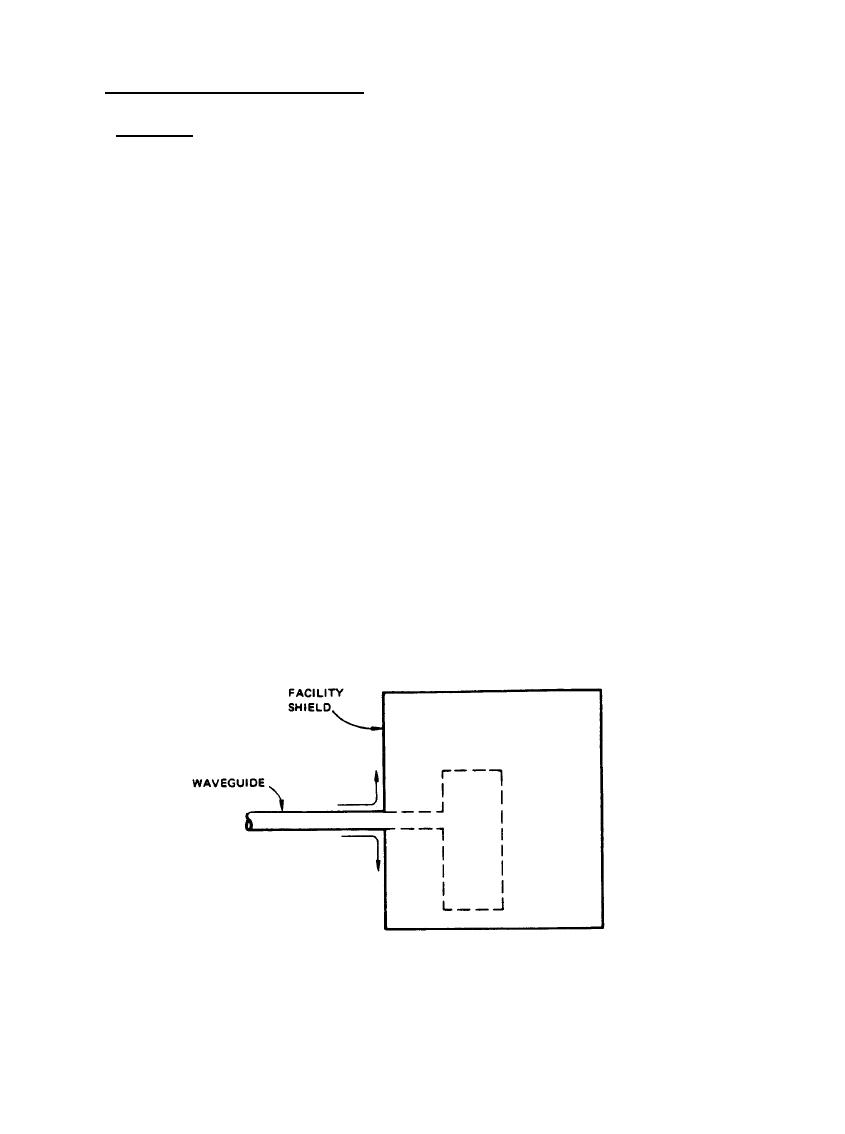
Waveguides, like other external conductors that penetrate the facility shield, can allow transients to propagate
into the facility if they are not made continuous with the shield in the manner illustrated in Figure 10-11.
Ideally, the waveguide wall should make continuous contact with the facility shield around the entire periphery
or the waveguide combination. All of the waveguide current would then flow onto the outer surface of the
facility shield; the external transients could only penetrate to the interior by diffusion through the waveguide or
facility wall.
In practice this continuous peripheral contact between the waveguide and the shield can be achieved by welding
or soldering the waveguide to the wall. Two ways of implementing this connection are illustrated in Figure 10-
12, where waveguide feedthrough sections are installed in the facility shield wall (or in a panel that is welded or
bolted to the wall). In both cases, a waveguide section with two flange joints is used to allow the internal
waveguide signal to pass through the wall but keep the external transient interference outside the facility. This
method of treating the waveguide allows some flexibility in the waveguide plumbing inside and outside the
facility, since only the feedthrough section is permanently attached to the wall.
For microwave receiving systems operating with very small signals, the fraction of a dB loss in the joints and
the possibility of additional loss from distortion about the weld may be undesirable, although the weld
distortions can be eliminated by machining or reforming the welding operation. Where these losses are
intolerable, some alternate methods of attaching the waveguide to the facility shield are available. In the
following sections, two of these methods are described. Although these methods can be used satisfactorily,
they are generally less rugged and more susceptible to corrosion and other degradation than the welded
feedthrough sections of Figure 10-12.
Figure 10-11. Exclusion of Waveguide Current from Interior of Facility
10-19
|
 |
|
 |
||