

Custom Search
|
|

|
||
 TM 5-683/NAVFAC MO-116/AFJMAN 32-1083
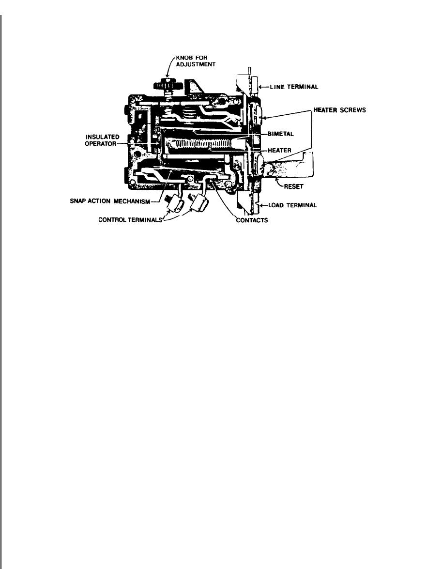
Figure 5-14. Typical terminal overload.
should be replaced to avoid possible misalignment
controller and motor should be located in the same
of an old contact with a new one. Check the contact
ambient temperature environment so that the over-
spring pressure with a scale in accordance with the
load relay can act accurately. If the controller is
manufacturer's recommendations. Adjust or replace
located in a lower ambient temperature environ-
the springs as necessary to maintain good pressure
ment than the motor, it may not trip in time to
between pairs of contacts. When copper contacts
protect the motor. Vice versa, if the controller is in a
become excessively rough, they should be smoothed
higher ambient temperature than the motor, it will
with a burnishing tool or a fine file designed for this
trip even if the motor is not in overload. The signifi-
purpose. Do not use emery cloth. Also, any copper
cant different ambient temperatures of the motor
oxide on the contact surfaces should be removed.
and controller can be compensated by selection of a
Copper oxide is not sufficiently conductive, it acts as
relay heater or use of a relay that compensates for
a high resistance and could eventually cause over-
temperature. The adjustments are to decrease the
heating. When filing, particular care should be
motor current protection (lower trip setting) by one
taken to maintain the original shape of the contacts.
percent for each degree Celsius the motor ambient
It is not necessary to develop smooth contact sur-
exceeds the controller normal ambient temperature
faces. In fact, better operation is obtained when the
or increase the motor current protection (raise trip
surfaces are rough dressed. Contacts should not be
setting) by one percent for each degree Celsius the
lubricated.
controller ambient exceeds the motor ambient. The
manufacturer's published heater selection tables
(2) Silver contacts. Silver contacts should not
be filed. Silver oxide, that forms on the contact sur-
should be referenced (fig 5-15). It should be noted
faces, does not have to be removed because it is a
that in this case, according to the National Electri-
cal Code, a disconnecting means must be located in
good conductor. Routine inspection should always
include checks for tightness of terminal and cable
sight from the controller location.
connections as well as for signs of overheating. Re-
f. Contractors. The part of the starter that con-
tains the coil and contacts is known as the contactor
placements should be made as conditions dictate.
Manufacturer's recommendations should be fol-
(fig 5-16). It is used to control the circuits to the
motor. Contractors are intended for repetitive opera-
lowed closely for maintenance and replacement of
tion, perhaps as many as a million or more opera-
parts.
tions. Normal wear and tear can be expected, and
(3) Shunts. Shunts are flexible bands of woven
therefore periodic inspections should be made to
copper strands carrying current from the moving
ensure that all moving parts are functioning. prop-
contacts to a stationary stud. If the shunt is unduly
erly.
bent or strands are broken, then it should be re-
placed.
(1) Copper contacts. Copper contacts should be
replaced when worn thin or badly burned and pit-
(4) Coils. Coils require very little maintenance.
ted. Both the moving and the stationary contacts
In fact it is generally more economical to replace the
5-14
|
 |
|
|
||


