

Custom Search
|
|

|
||
 TM 5-683/NAVFAC MO-116/AFJMAN 32-1083
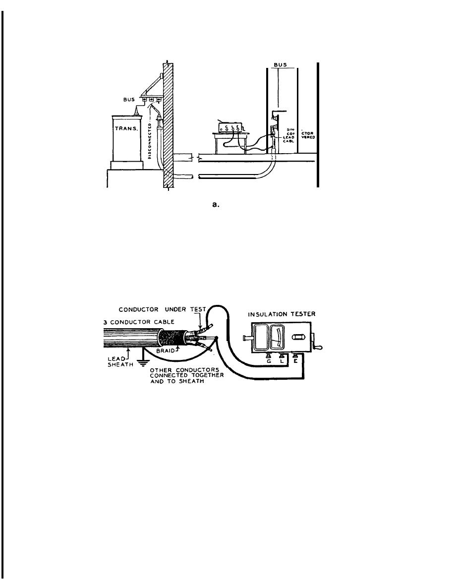
TESTER
b.
Figure 6-1. Connections for Testing Low Voltage Cable Insulation: a) Test on single-conductor cable, b) Tests on multi-conductor cable.
that persistent downward trends in insulation re-
mum) per 1,000 V of applied test voltage is ac-
sistance indicate insulation deterioration even
cepted. If a cable should fail the test, then further
though the readings may be higher than minimum
cable testing is required to pinpoint the failure loca-
acceptable values.
tion. A cable locator/fault finder can trace the exact
path of buried or above ground cable and locate a
6-4. Overpotential testing.
fault. The insulation resistance test should be per-
Both direct current (DC) and alternating current
formed at regular periods and a record kept of the
readings. Insulation resistance decreases with an
(AC) overpotential testing practices require the use
increase in temperature. Thus, in order to properly
of high voltages. Only properly trained, competent
interpret the results and to permit a reliable com-
shop personnel should perform such tests. Because
parison of periodic readings, the readings should be
of the extra time, manpower and expense needed for
corrected to a base temperature. Correction factors
overpotential testing, it is not recommended as a
and methods are shown in the reference material of
routine scheduled maintenance tool. The test is
the megohmmeter manufacturer. It should be noted
done mainly to seek out weaknesses in the cable
6-2
|
 |
|
|
||


