

Custom Search
|
|

|
||
 TM 5-683/NAVFAC MO-116/AFJMAN 32-1083
Care must be taken to remove all ground cables
(1) Ground cables. Ground cables must be sized
before the equipment is m-energized. It is recom-
for the maximum available fault current. Due to the
mended that all conductors be tested with a
wide range of system voltages and fault currents, no
megohmmeter to ascertain if any are still grounded.
published standards have been developed for spe-
cific applications or locations of grounding cables. A
(2) Ground clamps. Solid metal-to-metal con-
nections are essential between ground clamps (fig
general survey of commercially available grounding
12-4) and the de-energized equipment. Ground
and related safety devices shows use of 1/0 Ameri-
clamps should have serrated jaws because it is im-
can Wire Gauge (AWG) copper cables. This size ap-
practical to clean conductors from paint or corro-
pears to be a good compromise between a reason-
sion. The clamps should be tightened slightly in
able range of fault currents, the cable's ability to
place, given a rotation on the conductors to provide
safely conduct those currents given the thermal ca-
a cleaning action by the serrated jaws, and then be
pacity, and the ease of physically handling the par-
securely tightened. Ground clamps which attach to
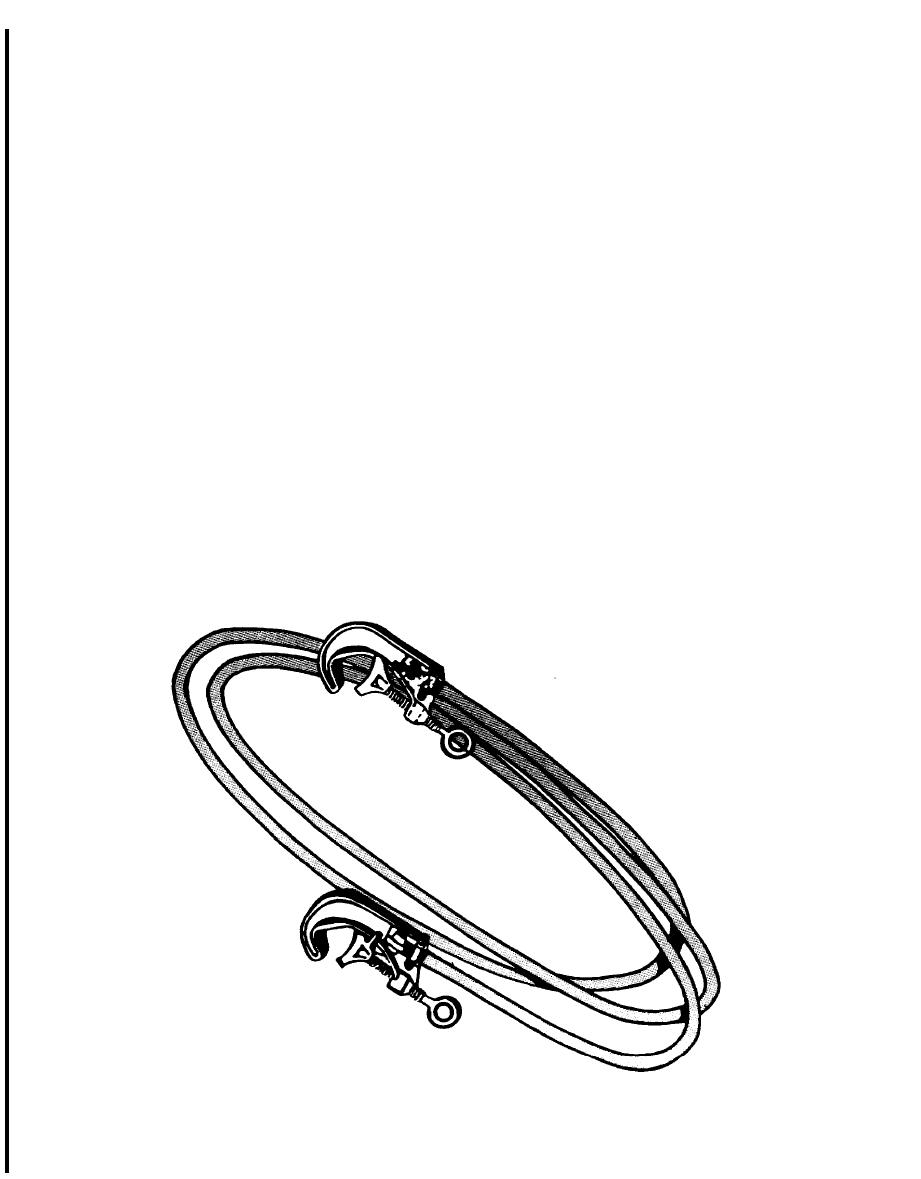
ticular size wire. Ground cables (fig 12-3) should be
switchgear ground bus are equipped with pointed or
no longer than necessary in order to keep cable
cupped set screws which should be tightened to
resistance as low as possible and to minimize cable
ensure penetration through corrosion and paint, to
slack thereby preventing their violent movement
provide adequate connections.
under fault conditions. Ground cables should be
connected first to the metal structure or switchgear
12-3. Switchgear.
ground bus and then to a phase conductor of the
The following precautions should be taken when
de-energized equipment. Then the ground cables
working on switchgear.
should be connected between phases and to the sys-
a. Before you work on the switchgear enclosure,
tem neutral (when available) to minimize the volt-
remove all drawout devices, such as circuit break-
a g e drop across the work area should re-
ers, instrument transformers, fuses and control
energization occur. When removing maintenance
power transformers.
grounds, the above procedure should be reversed.
Figure 12-3. Ground cable.
12-3
|
 |
|
|
||


