

Custom Search
|
|

|
||
 TM 5-6831/NAVFAC MO-116/AFJMAN 32-1083
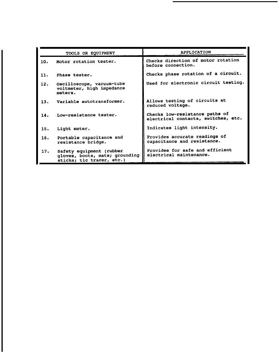
Table 13-1. Tools and equipment for effective electrical maintenance--continued.
the zero adjuster a sufficient amount to introduce
sire ohms range (fig 13-2). Plug a test lead in the
COMMON jack and another test lead in the + jack.
mechanical-freedom or "play'' but insufficient or dis-
Connect ends of test leads to short the VOM resis-
turb the position of the indicating pointer. This pro-
tance circuit. Rotate the ZERO OHMS control until
cedure will eliminate disturbances to the zero set-
pointer indicates zero ohms. If pointer cannot be
ting from subsequent changes in temperature,
adjusted to zero, one or both the VOM internal
humidity, vibration and other environmental condi-
batteries must be replaced. Before measuring resis-
tions. Once the VOM is zero adjusted, anyone ofa
dozen measurements canbe made. The two more
tance be sure power is off to the circuit being tested.
Disconnect the component from the circuit before
common tests are for AC voltage and resistance.
measuring its resistance.
(l) AC voltage measurement. Outlined below is
the procedure for measuring voltage in a circuit. Be
(b) Set the range switch to one of the resis-
tance range Positions.
careful when measuring line voltage, be sure that the
range switch is set to the proper voltage position.
(c) Set the function switch at either DC or
+ DC. Operation is the same in either position.
(a) Set the function switch at AC (fig 13-1).
Adjust ZERO OHMS control for each resistance
(b) Set the range switch at the desired voltage
range as described in (a).
range position. When in doubt as to the actual volt-
age present, always use the highes tvoltage range as
(d) Observe the reading on the OHMS scale
at the top of the dial. Note that the OHMS scale
a protection to the instrument. If the voltage is
within a lower range, the switch maybe set for the
reads from right to left for increasing values of re-
lower range to obtain a more accurate reading.
sistance.
(c) Plug a test lead in the COMMON jack
(e) To determine the actual resistance value,
multiply the reading by the factor at the switch
and another test lead in the + jack.
position.
(d) Connect the test leads across the voltage
(f) If there is a "forward" and "backward" re-
source.
sistance such as in diodes, the resistance should be
(e) Turn on power in the circuit being mea-
sured.
relatively low in one direction (for forward polarity)
(f) Read the value on the scale.
and higher in the opposite direction. Rotate the
(2) Resistance measurement. The procedure for
function switch between the two DC positions to
measuring resistance is outlined below.
reverse polarity. This will determine if there is a
difference between the resistance in the two direc-
must be adjusted to zero. Turn range switch to de-
tions.
13-3
|
 |
|
|
||


