
Custom Search
|
|

|
||
 TM 5-683/NAVFAC MO-116/AFJMAN 32-1083
Earth surface
Electrode
/
Hemispheres
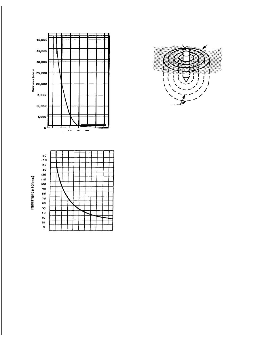
Figure 14-8. Earth electrode with hemispheres.
(c) At stations where the fence is not con-
nected to the station ground, a dangerous voltage
can develop under fault conditions between the
Figure 14-6. Soil resistance vs. temperature of clay soil.
fence and station ground. Do not touch both at the
same time.
(d) Surge and switching effects in transmiss-
ion lines may induce dangerous spikes in the test
leads strung under the line. Care should be exer-
cised in handling these test leads.
(e) Tests should not be performed during a
thunderstorm.
(2) Protection. Rubber gloves, boats, an insu-
lated platform, etc., capable of protecting the opera-
tor against full-line voltage, are recommended for
protection.
(3) Fall-of-potential method. The fall-of-
potentiaI method is probably the most widely used
and accepted of all methods available. It can be
used most practically on small and medium sized
systems. A ground resistance test set is used. Meas-
ure the earth resistance of the earth system (E) (fig
3
4
5
6
7
0
1
2
8
9
10
14-9). In this method, greater pin spacing is re-
quired for testing ground grids and multiple rod
Depth of electrode in feet
installations than for single rod testing. To accom-
Figure 14-7. Soil resistance vs. depth of electrode.
plish this, current is supplied between the current
electrode (CE) and the system E under test. A volt-
(a) When testing earth resistance, remember
meter measures the voltage drop between the po-
that during fault conditions, dangerous voltages
tential electrode (PE) and the system. By moving
may exist between a system ground and a remote
the potential electrode between E and CE, various
point being tested. Care should be taken when con-
voltages will be recorded and corresponding resis-
necting leads and test equipment, Avoid as much
tance values found. When the resistance values are
contact with the leads and probes as possible.
plotted versus distance, the earth resistance can be
seen to increase as the potential electrode moves
(b) Most of the earth resistance is located
close to the grounding system due to the "hemi-
away from the system ground, but at a decreasing
sphere effect". When a ground fault occurs, the ma-
rate of change. This results because each new outer
jority of the voltage drop is close to the system.
hemisphere of earth around the system E adds a
Caution should be used when approaching a live
smaller amount of resistance to the total earth re-
ground.
sistance as previously discussed. At a point, usually
14-6
|
 |
|
 |
||