

Custom Search
|
|

|
||
 TM 5-684/NAVFAC MO-200/AFJMAN 32-1082
a. Insulation resistance test. Routine insula-
by overheating, and tracking and carbonization.
Look for cracked or chipped insulators; loose insula-
tion resistance tests on transformers are normally
tors, clamps, or coil spacers; deterioration of barri-
made at voltages given in table 3-4. Insulation
ers; and corroded or loose electrical connections.
resistance usually decreases somewhat with an
(13) Cleaning and other dry-type transformer
increase in applied voltage. However, for a varia-
requirements. Dirt and dust should be removed from
tion of two to one or three to one in the usual test
the windings with a vacuum cleaner. Compressed
voltage ranges, there is no appreciable effect on
air may be used after vacuuming, but only if it is
insulation resistance for equipment that is in
clean and dry and applied at a low pressure to avoid
good condition. Marked variations in insulation
damage to windings. In particular, ventilating ducts
resistance for different values of voltage are usually
and the top and bottom of the windings should be
due to the effects of dirt or moisture. The insula-
cleaned. The use of liquid cleaners should be em-
tion resistance values for oil-filled transformers
ployed only when it is known that they will not have
will vary due to humidity, size and type of trans-
a deteriorating effect on the insulation.
former, temperature, and the value the test voltage
(a) Operation. Best service life will result if
applied.
the windings are maintained above the ambient
(1) Records. A record should be made of all
temperature level. For this reason, transformers op-
factors for comparison with previous and future test
erating in high humidity should be kept energized,
results. Temperature correction factors are indi-
if feasible. If a transformer is to be de-energized
cated in table 7-2. To obtain the equivalent insula-
long enough for it to cool, special drying procedures
tion resistance at 20 degrees C, multiply the insula-
may be required before the transformer is re-
tion resistance reading in megohms by the
energized. Refer to the manufacturer's recommen-
appropriate correction factor. Values of winding in-
dations for drying procedures to be followed.
sulation resistance may be affected by residual
(b) Sealing. Sealing severe leaks, or opening
charges that are retained in the winding. For this
and resealing the tanks of sealed dry-type trans-
reason, windings should be discharged to the frame
formers, requires special procedures and equip-
until the discharge current reaches a negligible
ment. The manufacturer of the transformer, an ex-
value. Ten minutes or more may be required to
perienced transformer repair facility, or a qualified
complete the discharge.
electrical maintenance contractor should perform
(2) Insulation testers. Resistance testers are
this work.
available that indicate directly in ohms the resis-
(c) Special procedures. In addition, special
tance being measured. The power source necessary
procedures covering drying out of the windings, and
for operation of the tester may be a hand cranked
purging and refilling of the tank, may be required.
generator, motor operated generator, or rectifier
7-6. Transformer testing guidance.
supplying a direct-current voltage for test purposes.
For best results, the detailed instructions furnished
All tests should meet the requirements of
with each of these instruments should be followed.
ANSI/IEEE CF57.12.90 for liquid-immersed trans-
formers and IEEE (X7.12.91 for dry-type trans-
formers. Expanded explanatory data for tests can
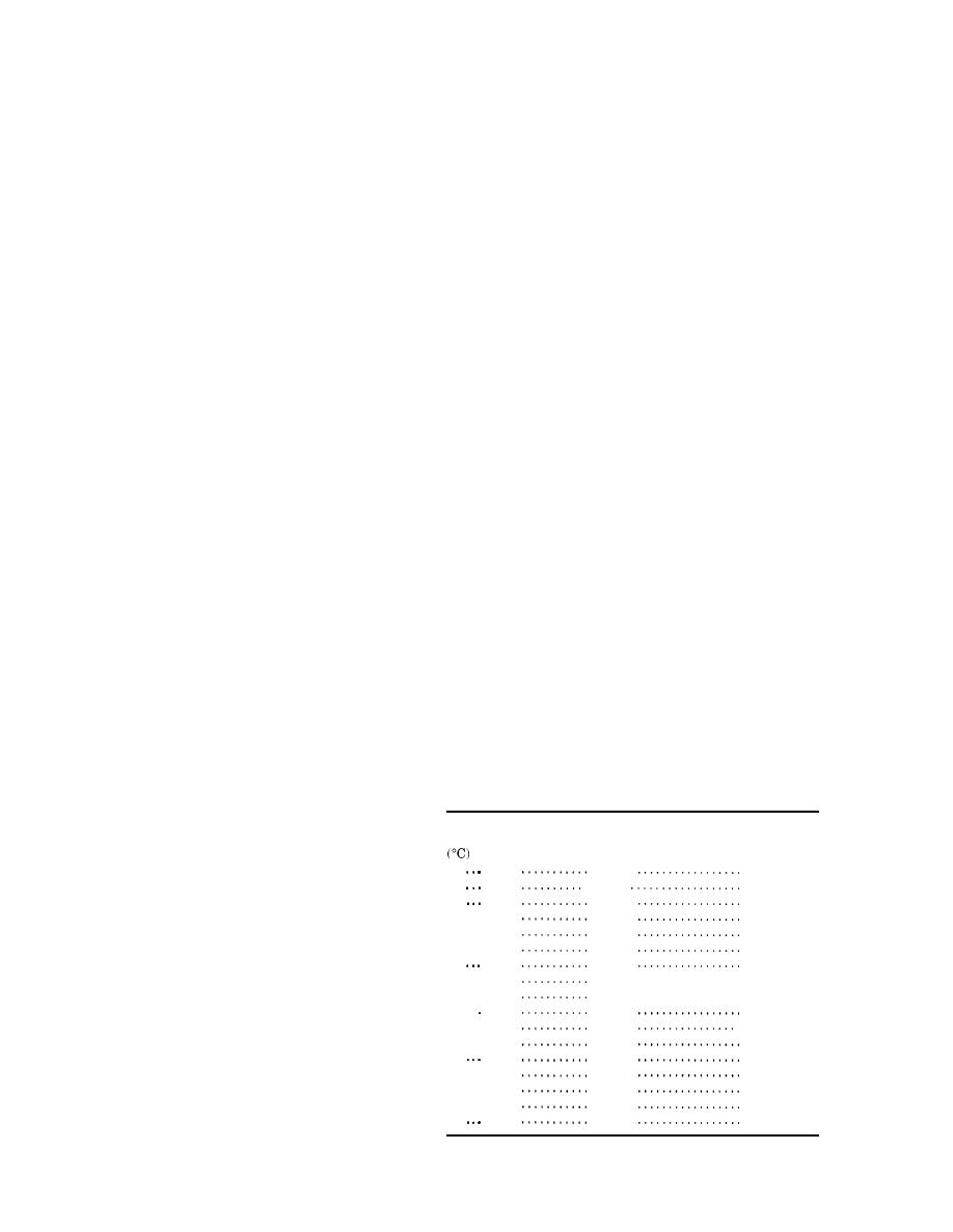
Table 7-2. Insulation resistance conversion factors to 20C
also be found in NFPA 70B and "Electrical Equip-
Temperature
Transformer
ment Testing and Maintenance."
Oil
Dry
7-7. Solid (winding) insulation tests.
0.25
0
0.40
0.45
5
0.36.
Nondestructive tests for the dielectric properties of
10
0.50
0.50
solid insulation include the insulation resistance
15 . . .
0.75
0.75
test, the dielectric-absorption test, and the power
20 . . .
1.00
1.00
factor test. High potential and induced potential
25 . . .
1.30
1.40
tests can cause damage to the insulation. However,
30
1.60
1.98
35 . . .
2.80 . . . . . . . . . . . . . . . . .
these tests do discover weakened insulation, and
2.05
40 . . .
2.50
3.95 . . . . . . . . . . . . . . . . .
any damage is usually much less than that caused
45 . .
5.60
3.25
by an in-service failure. Insulation tests can be ap-
50 . . .
7.85
4.00
plied to dry-type transformers; however, the voltage
55 . . .
5.20
11.20.
impulse values should be lower than those used for
60
6.40
15.85
65 . . .
22.40
liquid-immersed transformers. A transformer turns
8.70
70 . . .
31.75
10.00
ratio test can identify trouble in transformer wind-
75 . . .
44.70
13.00
ings; its use in proof testing is generally limited to
80
63.50
16.00
dry-type units.
7-6
|
 |
|
|
||


