

Custom Search
|
|

|
||
 TM 5-684/NAVFAC MO-200/AFJMAN 32-1082
Table 11-l. Typical laboratory relay test equipment
115 VOLTS. 60 HZ
Test equipment
Description
115 volt, 5 and 15-20 amperes
Variable voltage
autotransformer
3-15-150 volt, 5000 ohms
Multirange dc voltmeter.
0-2-5-l0-20-50-100-200 am-
Multirange ac ammeter
peres
0-3-7.5-30-75-150-300 volts
Multirange dc voltmeter.
0-5-20-50-amperes
Multirange dc ammeter
5-10-30 amperes, 15-30-50-
Phase angle meter
120-240-480 volts, 60 hertz
Auxiliary current transformers 1-5-10-25-50-62.5-125-250-
500/5 amperes
Cycle counter or timer.
0 - 1 0 seconds, 120 volts
RELAY
three-phase, 500 watts
Phase shifter
Multirange noninductive load
0-100 amperes range
resistor
R
Three-phase sequence indica-
110-550 volts, 25-60 hertz
tor..........................
Auxiliary relays, dc
125 volt
satisfactory, provided the shaft or bearings have not
been disturbed. In any case, the manufacturer's di-
rections should be followed.
e. Performance check. Upon completion of repair
work, complete performance tests should be made
on the relay, even though the work done may not
appear to affect relay operation. It is possible that
during repair, other adjustments or alignment of
relay parts may have been changed or affected. Af-
ter an overhaul, the tests made should not be less
thorough than the relay's original acceptance tests.
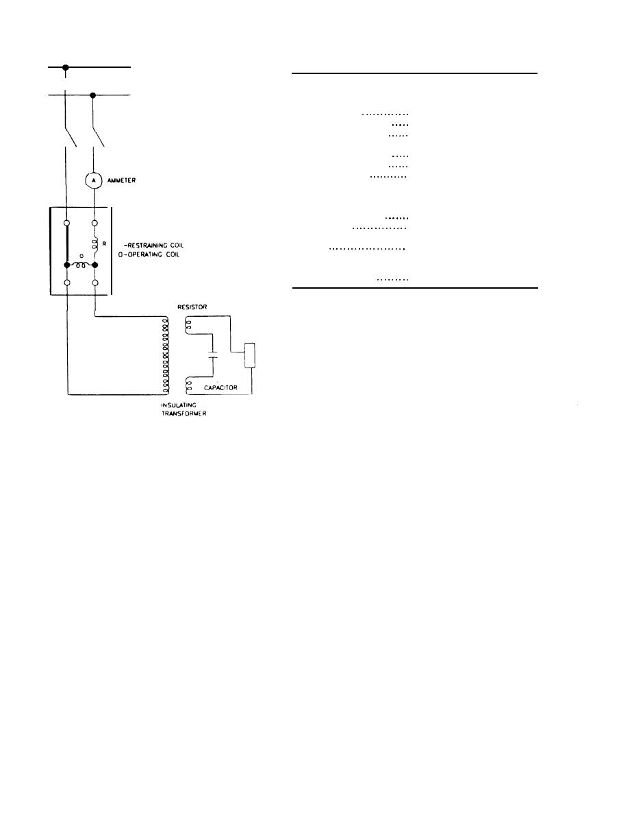
Figure 11-5. Typical test connection for a pilot wire relay
Section II-CONTROLS
11-10. Control functions.
much greater degree by ambient temperature
changes and excessive electrical circuit parameters.
Controls are broadly defined as the methods and
b. Power supply. Control equipment may be pow-
means of governing the performance of any electric
ered from storage batteries or from an ac source.
apparatus, machine, or system, by sensing any need
Controls will only be as dependable as their operat-
for a change and facilitating that change. In per-
ing input. The power supply must be as reliable as
forming these duties, control circuits or systems
possible, so that control and protection of the equip-
may act to regulate, protect, indicate, open, close, or
time an operation. Control devices execute control
ment is not jeopardized. See chapter 14 for details of
functions.
battery maintenance and repair.
a. Control equipment. Some of the more common
c. Control lines. Pneumatic and electromagnetic
equipment controlled are switches, circuit breakers,
controls are gradually being replaced by electronic
contactors, lights, rheostats, timers, and valves.
loop controls, as systems are increasingly being in-
Control schemes use combinations of the following
corporated into energy management control sys-
component parts to produce the desired operation:
tems (EMCS) or supervisory control and data acqui-
alarms, batteries, coils, fuses, relays, solenoids, tim-
sition systems (SCADA). Sensors are used to
ers, switches, and transformers. Other special elec-
provide units of information via conventional (hard)
trical equipment may be used also.
wiring to the field interface devices (FIDs). A sensor
(1) Electromechanical controls. Electrome-
is installed as a component part of the electrical
chanical controls are operated by magnets, thermal
apparatus being controlled and must be maintained
action, motors, or other mechanical or static actions.
by electrical maintenance personnel. Control line
(2) Solid-stat e controls. Solid-state controls
components such as FIDs, data transmission links,
the central processing unit (CPU) and its subcompo-
perform similar functions to electromechanical con-
nents are not electrical maintenance responsibili-
trols, but their characteristics are affected to a
11-6
|
 |
|
|
||


