

Custom Search
|
|

|
||
 Section 2. ROTARY SLIDING VANE COMPRESSORS
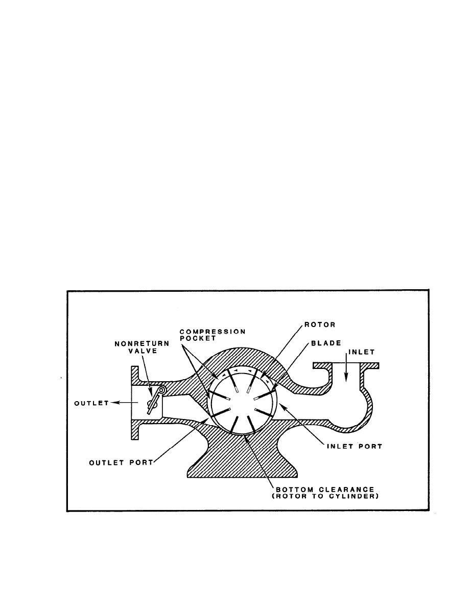
1 DESCRIPTION. Rotary sliding vane compressors (figures 2-6 and 2-7) consist
of a cylindrical casing in which an eccentrically mounted rotor is located.
The rotor is fitted with blades that are free to slide in and out of
longitudinal slots. In operation, the blades are forced outward by
centrifugal force and form compartments where air is compressed. Each
compartment varies from a maximum volume on the suction side of the revolution
to a minimum volume on the compression half of the revolution. This gives a
positive displacement type suction and pressure effect. Rotary sliding vane
machines are normally directly connected to electric motors or internal
combustion engines. Operating and maintenance instructions for electric
motors and internal combustion engines are contained in NAVFAC MO-205, Central
Heating and Steam Electric Generating Plants.
2 STARTUP.
2.1 Prestart Inspection. Carefully inspect the compressor installation to
ensure the following prestart requirements are fulfilled.
(a) All installation and repair work has been completed.
(b) Installation has been cleaned and tested for leaks.
(c) Alignment has been checked.
(d) Unit is properly lubricated; crank lubricator by hand to clear lines
of air and to assure oil supply for startup.
FIGURE 2-6. Cross Section of Rotary Sliding Vane Compressor
2-13
|
 |
|
|
||


