
Custom Search
|
|

|
||
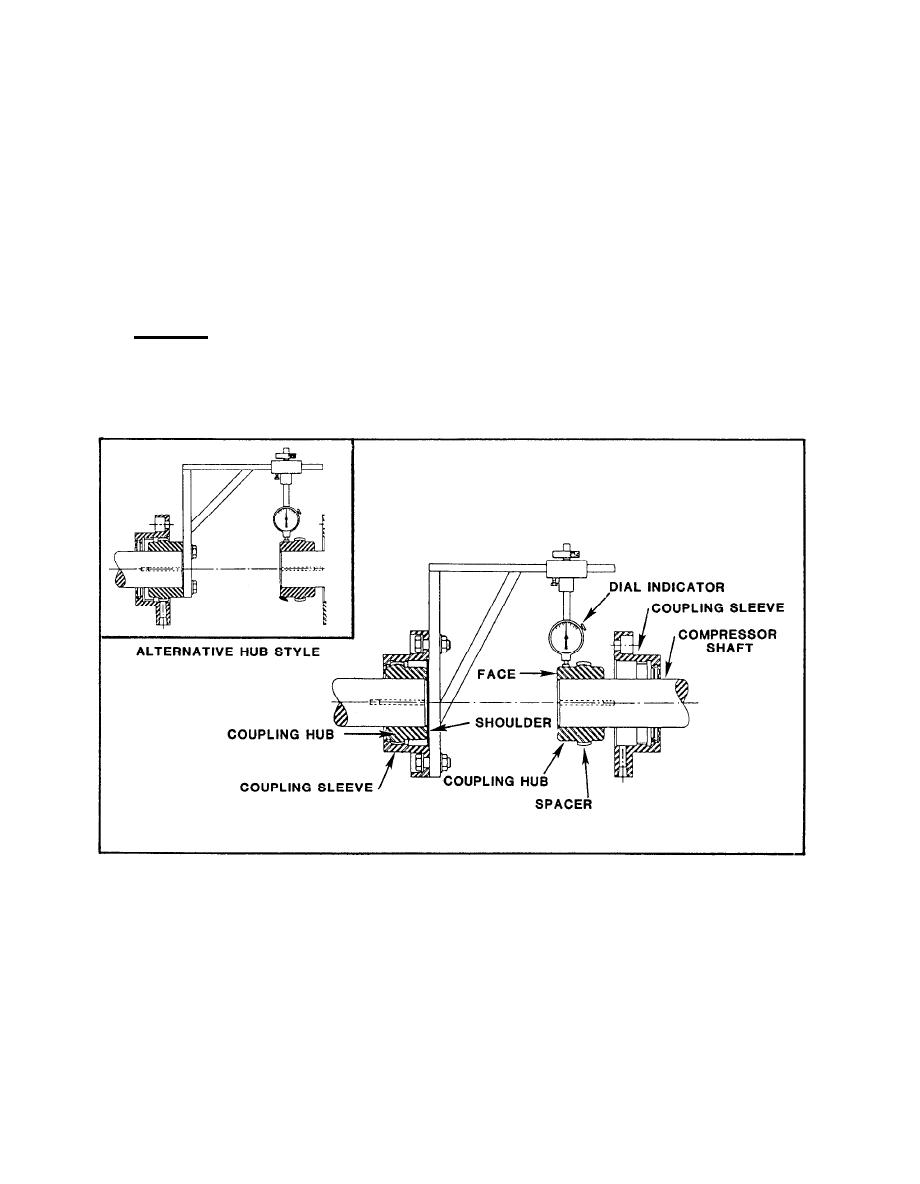
 (b) Attach dial indicator to mounting bracket with the pointer
contacting the shoulder on the coupling hub.
(c) Rotate compressor shaft and take readings 90 apart.
(d) Correct axial misalignment by adding or removing shims under the
driver to bring compressor and drive centerlines into alignment.
(e) To check angular alignment, follow the above procedure, but take
indicator readings on the coupling hub face (figures 3-6 and 3-7).
(f) To correct angular misalignment, parallel the coupling faces by
shifting the drive on its base and adding or removing shims under the driver
base.
7.3 Bearings. Centrifugal and axial flow compressors utilize many bearing
types such as: split sleeve, steel backed babbit inserts, tilting pad, and
antifriction roller and ball bearings. Use specific manufacturer's
information for bearing wear, adjustment, and replacement considerations.
FIGURE 3-6. Alignment Setup
3-11
|
 |
|
 |
||