

Custom Search
|
|

|
||
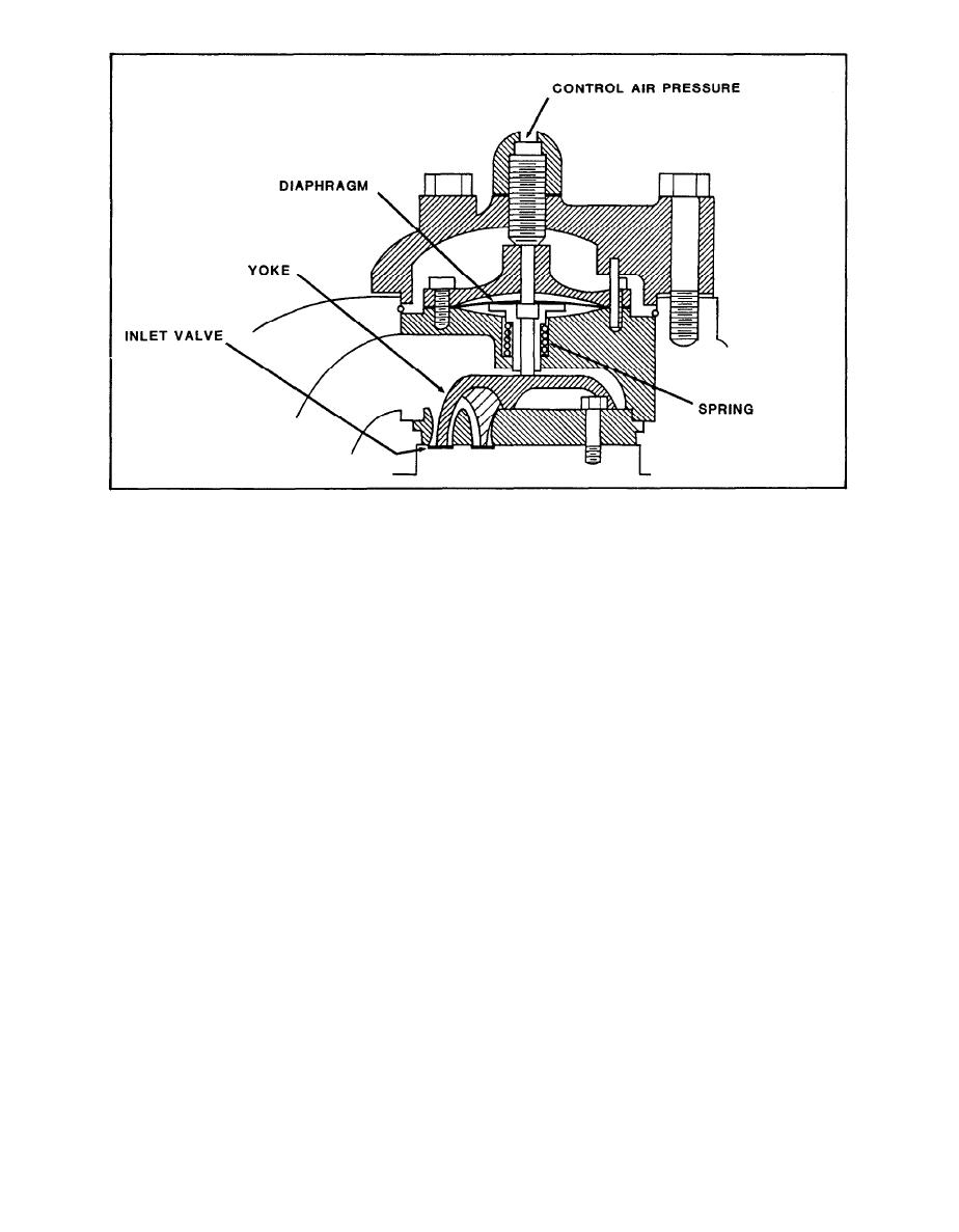 FIGURE 5-3. Inlet Valve Unloader
(2) To understand the operation of this five-step control system
which combines the components previously described, refer to figure 5-4. When
the compressor is started, the air pressure switches are closed and the
solenoids in the unloader valves become energized so that receiver pressure
cannot enter the unloading lines and compression is allowed to take place. As
receiver pressure builds up and reaches 97 psi, APS No. 1 breaks contact,
deenergizing the unloader and allowing 97 psi receiver air to enter control
line No. 1, actuating the inlet valve unloader. Twenty five percent of the
compressor has become unloaded and compression has been reduced from full to
75 percent capacity. Control lines Nos. 2, 3, and 4 operate in the same way
as receiver pressure increases. At 100 psi, all cylinders are unloaded and
air compression ceases, but the compressor continues to run under no load. As
air is drawn off from the receiver, the pressure begins to drop. When the
pressure falls to 96 psi, APS No. 4 makes contact and energizes the unloading
of valve 4, which cuts off receiver pressure from the inlet unloader and vents
the unloader pressure to atmosphere. The inlet valve unloader releases the
inlet valve and normal compression takes place, loading the compressor to 25
percent capacity. If the demand for air increases and receiver pressure
continues to decrease,control lines Nos. 3, 2, and 1 will load in sequence.
5-8
|
 |
|
|
||


