

Custom Search
|
|

|
||
 Finally, closed-loop systems require a fill/drain assembly to allow adding the solar
fluid while removing air. Normally, this assembly consists of two boiler drains (or
hose adapters with shutoff valves) on each side of a shutoff valve. In many cases,
the check valve is used between the fill/drain ports in place of a shutoff valve.
Because collectors in a closed-loop system do not need to drain themselves on a
regular basis, the location of the collectors relative to the rest of the system is not
critical. Compare this to other types of systems, where the location of the collector is
critical to proper system performance.
2.3 BASIC CONFIGURATION OF DRAINBACK SYSTEMS
Drainback systems use water as the collector fluid. The collectors and exposed
piping must be installed so proper draining is possible to avoid freezing.
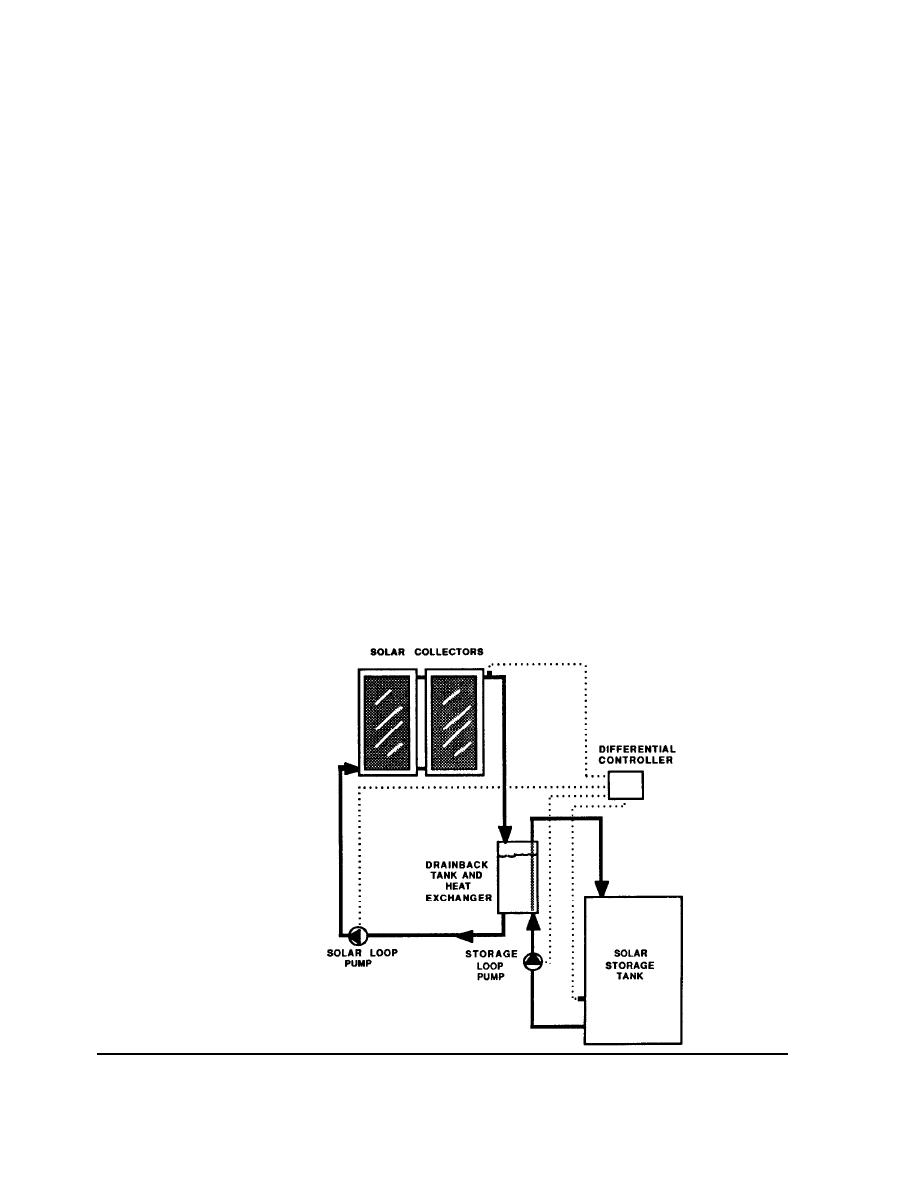
Looking at Figure 2-12, you can see how the water from the collectors drains back
into a reservoir tank whenever the solar loop pump is turned off. The reservoir tank
is large enough to accept the volume of water held in the collectors and exposed
piping.
When solar energy is available for collection, the solar loop pump pushes water up
the system to the top of the collectors, where it drops back into the reservoir to be
pumped back up again.
FIGURE 2-12
A Drainback Solar
Heating System
OPERATION
16
2.3 DRAINBACK SYSTEMS
|
 |
|
|
||


