

Custom Search
|
|

|
||
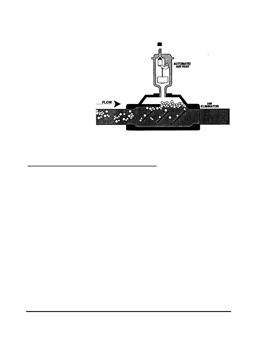 FIGURE 2-40
An Air Eliminator
Collector Loop Control Valves for Draindown Systems
Draindown systems can be emptied and filled by a single control valve, or a group
of three individual solenoid valves. In either approach the system control operates
the valve package, draining the collectors and exposed piping during times of
freezing temperatures, and refilling it during warmer periods.
Larger systems use two normally closed solenoid valves and one normally open one
in the configuration shown in Figure 2-41. When outdoor temperatures are above
freezing the two normally closed valves are open, allowing water from the tank to fill
the collector loop. The normally open valve in the drain line is closed, keeping water
in the system.
To drain the collectors and exposed piping, the power to all three valves is turned
off. Normally closed valves keep water out of the collectors. The normally open
valve allows water to drain from the collectors. This water is not recovered, and is
piped to a drain. The system is considered "fail-safe," because under normal failure
modes, such as a power failure, the system will drain, thus failing in a safe state.
Standard solenoid valves are typically used in this type of system. For adequate
flow, a minimum of 1/2 inch or 3/4 inch ports are required. The solenoids are
usually 120 volts, and wetted materials are normally brass or stainless steel.
OPERATION
44
2.7 COMPONENT OPERATION
|
 |
|
|
||


