

Custom Search
|
|

|
||
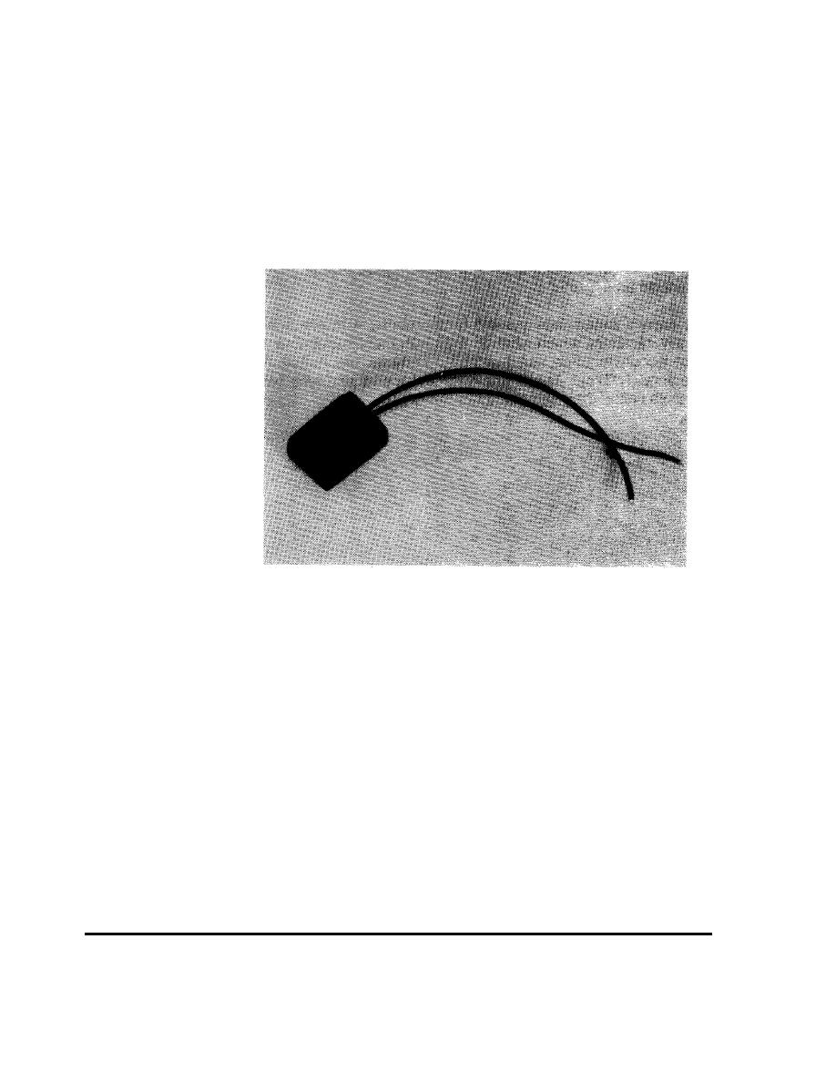 One exception is the collector sensor on pool heating systems. It is not attached to
the collector. It is built and mounted on the roof or rack next to the collectors.
Because it has nearly the same thermal characteristics as the collectors, it
"impersonates" the collector temperature for the control to use. (Figure 2-48)
Controls and sensors are available in two types: 10K and 3K. These refer to the
resistance the temperatures have at "room" temperature (77F). A 10K sensor has
10,000 ohms resistance at this temperature, a 3K has 3,000 ohms.
FIGURE 2-48
A Pool System
Collector Sensor
Normally, the sensors operate at only a few volts. This means sensor wiring is
considered Class 2, and thus does not require conduit or armor. However, this low
voltage wiring is susceptible to electrical "noise" from 120, 240 and higher voltage
wiring, electric motors, radio transmitters and other sources of RF (radio frequency)
noise.
The usual solution to this problem is to maintain adequate distance between the
controls, sensors and wiring, and the source of noise. If this is not possible,
shielded cable is used.
Most controls have
a three-position switch with the functions marked "on," "off," and
"auto." In the "on"
position, the control ignores the sensor signals and operates the
pumps constantly.
In the "off" position, the sensor signals are ignored, and the
pumps remain off.
The "auto" position is used for normal, automatic operation.
(Figure 2-49)
OPERATION
52
2.7 COMPONENT OPERATION
|
 |
|
|
||


