

Custom Search
|
|

|
||
 Use Table 3-3 or 3-4 to determine the right resistance to use to simulate a particular
temperature. An abbreviated version, with resistor color codes, is presented in
Table 4-3.
Controls . Tester Method
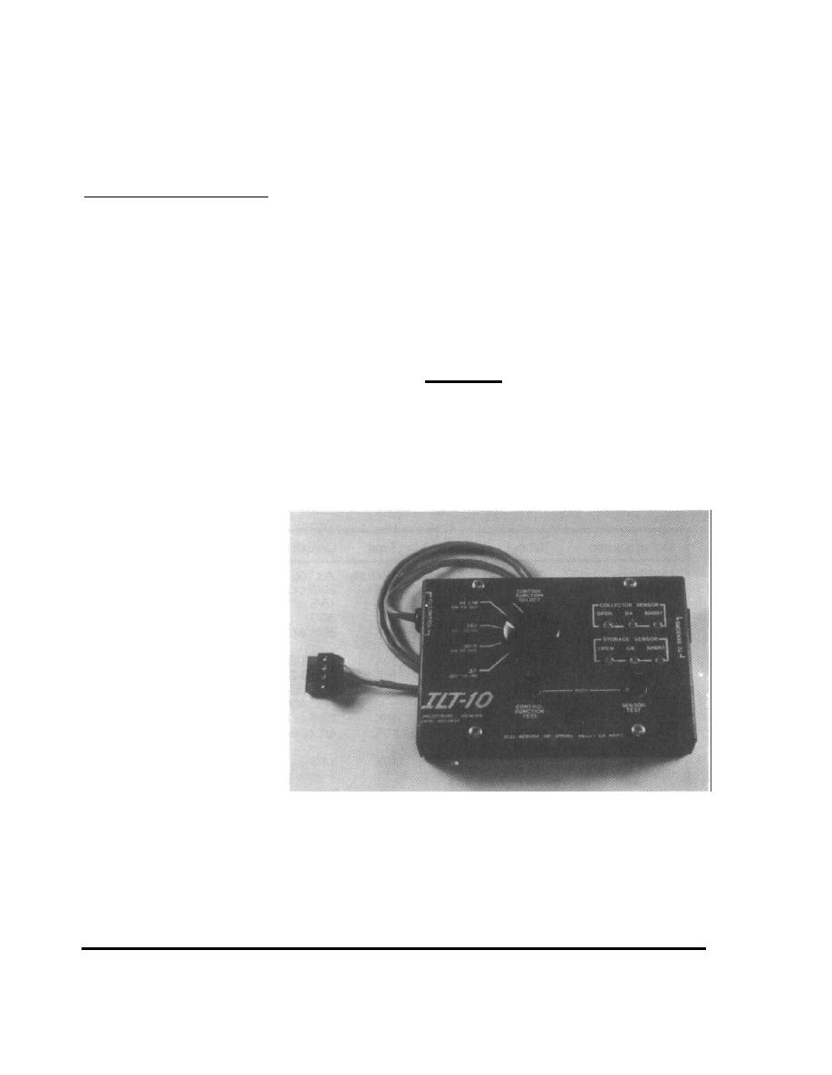
A more accurate method of testing differential thermostats is with a special tester
designed for the purpose. Normally, these units have four leads or terminals.
These are connected to the collector and storage sensor terminals of the control.
The tester supplies a calibrated resistance to the two sensor inputs to simulate
changing sensor temperatures. (Figure 3-20)
Most of the available testers supply a fixed resistance to the storage terminals and
change the resistance supplied to the collector terminals. The numbers on the
tester dial usually refer to the temperature difference between the storage and
collector terminals.
As the tester dial is slowly turned to greater temperature differential settings, the
resistance supplied to the collector sensor terminals is lowered. At the "on"
differential, the control should turn on.
FIGURE 3-20
Solar Control
Tester
INSPECTION
88
3.1 INSPECTION PROCEDURES
|
 |
|
|
||


