

Custom Search
|
|

|
||
 TM 5-685/NAVFAC MO-912
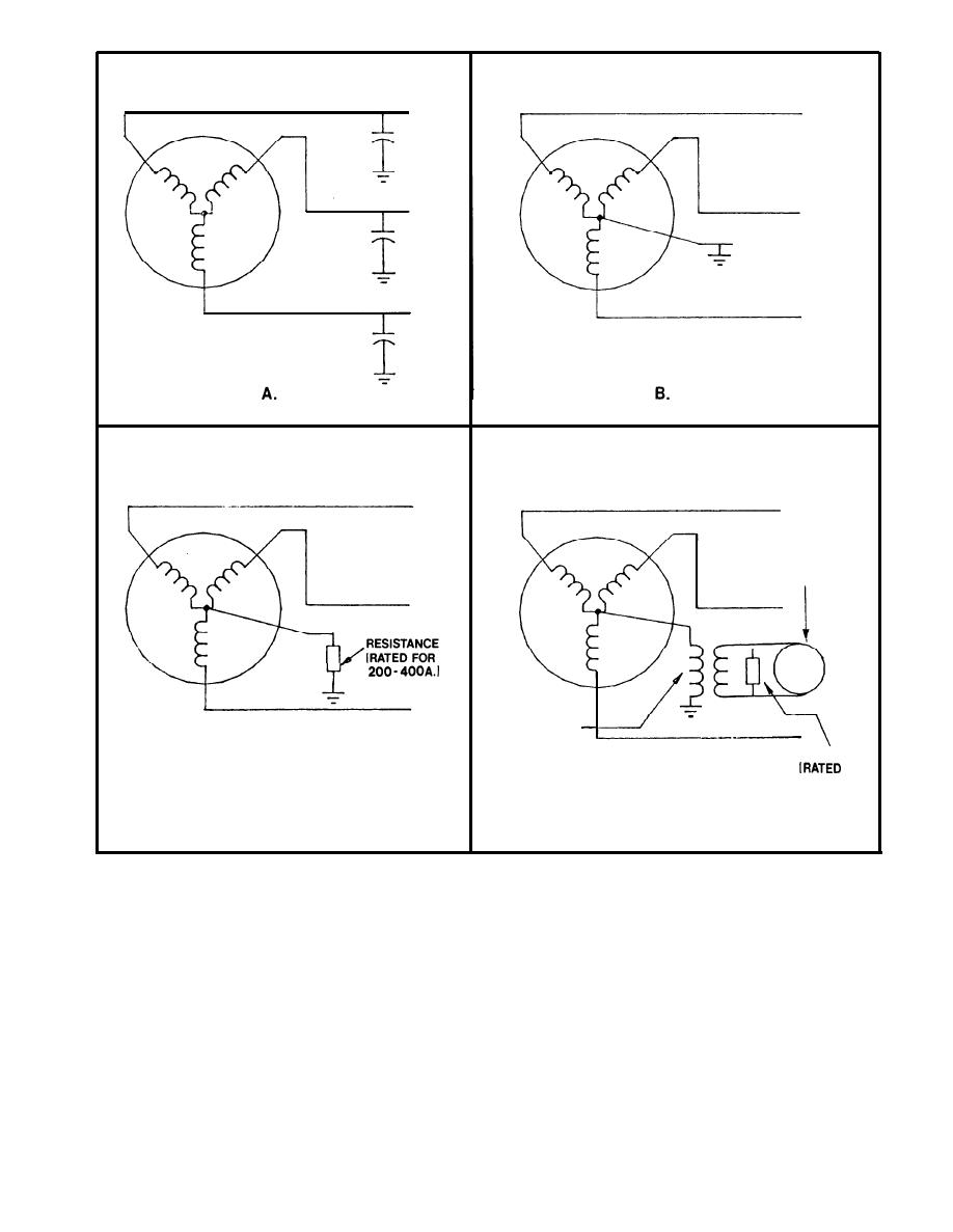
VOLTAGE
RESISTOR
FOR
2 TO 6A.I
C.
D.
Figure 2-2. Types of system grounding.
A) UNGROUNDED GENERATOR, B) SOLIDLY GROUNDED, C) LOW RESISTANCE GROUNDING,
D) HIGH RESISTANCE GROUNDING
be close to ground potentials because of the ca-
line voltage (i.e., square root of three (3) times
pacitance between each phase conductor and
the normal line-to-neutral value). Over a period of
ground. When a line-to-ground fault occurs on
time this breaks down the line-to-neutral insulation
an ungrounded system, the total ground fault
and results in insulation failure. Ungrounded sys-
current is relatively small, but the voltage to ground
tem operation is not recommended because of the
potential on the unfaulted phases can reach an
high probability of failures due to transient
unprecedented value. If the fault is sustained,
over-voltages (especially in medium voltage i.e., 1
the normal line-to-neutral voltage on the un-
kilovolt (Kv)-15 Kv) caused by restriking ground
faulted phases is increased to the system line-to-
faults.
2-5
|
 |
|
|
||


