

Custom Search
|
|

|
||
 TM 5-685/NAVFAC MO-912
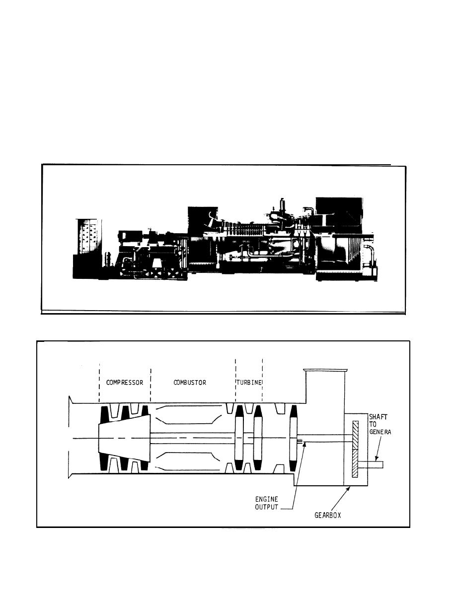
3-15. Principles of operation.
the combustor provide a spark to ignite the fuel/air
mixture for engine start-up. The igniters are deac-
a. Components. A typical gas turbine engine con-
tivated after start-up has been accomplished. Hot
sists of a compressor, combustor and turbine (see fig
combustion gases are expelled through the turbine.
3-20).
(3) The turbine extracts energy from the hot
(1) The compressor is driven by the turbine
gases, converting it to rotary power which drives
through a common shaft. Air enters the compressor
the compressor and any load, such as a generator.
via an inlet duct. The compressor increases the air
Exhaust gases are vented via ductwork to the atmo-
pressure and reduces the air volume as it pumps air
to the combustor and through the engine.
sphere.
(2) Fuel (liquid and/or natural gas) is delivered
(4) The air intake for a gas turbine engine usu-
to the combustor by a fuel system consisting of a
ally consists of a plenum chamber with a screened
manifold, tubes, and nozzles. Electrical igniters in
inlet duct opening. The plenum chamber and duct
Figure 3-19. Typical gas turbine engine for driving electric power generator.
DUCT
I
I
TOR
INLET
DUCT
SHAFT
Figure 3-20. Gas turbine engine, turboshaft.
3-28
|
 |
|
|
||


