
Custom Search
|
|

|
||
 TM 5-685/NAVFAC MO-912
various relays and indicating lights associated with
the control circuitry. The control circuits are classi-
fied as either AC or DC.
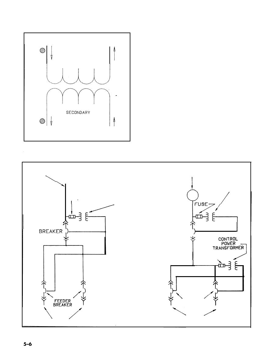
(1) ACcontrol circuits. AC control circuits usu-
__
PRIMARY
ally derive their power from the source side of the
circuit breaker being controlled. This procedure ap-
plies to main incoming line circuit breakers, genera-
tor circuit breakers, and feeder circuit breakers (see
fig 5-6). Depending on the system voltage, the con-
trol power can be taken directly from the main bus
since it can be connected through a control power
transformer.
(2) Tie break er control circuits. In systems us-
ing a tie breaker, the control power for the tie
breaker and the feeder breakers is supplied through
a throw-over scheme so control power is available if
either side of the tie breaker is energized (see fig
5-7). In applications that require synchronizing cir-
cuitry, the running and incoming control buses are
usually supplied via the potential transformers. The
transformer primaries are connected to both the
line side and the load side of the circuit breakers
Figure 5-5. Current flow in instrument transformers. `Polarity"
that are used for synchronizing. The transformer
marks show instantaneous flows.
MAIN INCOMING LINE
CONTROL
POWER
TRANSFORMER
FUSE
CONTROL POWER
TRANSFORMER
CONTROL
MAIN
GE N E R A T O R
POWER
BR E A K E R
BUS
I
FUSE,
FEEDER
BREAKER
LOAD
LOAD
Figure 5-6. AC control circuits.
|
 |
|
 |
||