

Custom Search
|
|

|
||
 TM 5-683/NAVFAC MO-116/AFJMAN 32-1083
I
6
4
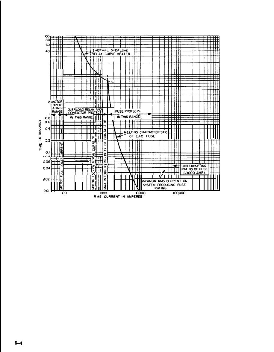
Figure 5-4. Coordination of motor overload relay and current limiting fuse.
rents. At military installations, they typically range
with taps which allow them to be adjusted to oper-
in size from 5 to 200HP, and the voltage may vary
ate at different percents of line voltage. Small sizes
from about 208V tQ 2300V. The autotransformer
are normally equipped with taps for 65 and 80 per-
starter provides greater starting torque per ampere
cent of line voltage, while larger sizes normally
of starting current drawn from the line than any
have 50, 65, and 80 percent taps.
other reduced voltage motor starter. Two contractors
(2) Resistance starters. This starter limits the
are usually u s e d f o r c o n n e c t i o n o f a n
starting current by employing resistors in series
autotransformer starter. See figure 5-5. When the
with the motor windings. This provides a smooth
start push button is pressed, start contactor "S"
start and precise acceleration through a closed tran-
closes. This contactor serves to connect the auto-
sition to full voltage and avoids a sudden mechani-
transformer to the line, and the motor to taps on the
cal shock to the driven load. Power and control
autotransformer. After a defined timely delay gov-
circuits of a resistance motor starter are given in
erned by pneumatic timer TR, contactor "S" drops
figure 5-6. When the start button is pressed, start
out, and run contactor "R" closes, connecting the
contactor "S" connects the motor to the line with the
motor directly across the line. At this time, the
starting resistor in series and a pneumatic timer is
autotransformer is disconnected from both the line
also picked up. After a time delay governed by timer
and the motor. It is important that contactor "S" is
TR, the TR/TC contacts close, Run contactor "R"
dropped out before contactor "R" closes since any
closes, short-circuits the starting resistor, and con-
overlapping of "R" and "S" in the closed position will
nects the motor across the line.
result in a short circuited autotransformer second-
(3) part-winding starters. These are used with
ary. This would cause high current to flow and sub-
squirrel cage motors having two separate, parallel
ject that winding to high thermal and magnetic
stator windings (fig 5-7). The motor is started on
stresses. Standard autotransformers are equipped
one winding through accelerating contactor "lM" at
|
 
|
|
|
||


