

Custom Search
|
|

|
||
 MIL-HDBK-1013/10
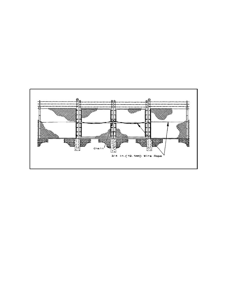
a barrier across the opening. Once the chain and wire rope has been installed
as shown in Figure 22, the energy of a vehicle crash attempt is transferred
from the gate through wire rope links to the side gate posts, and further to
the fence cable reinforcement system and deadman concrete anchors. The fence
reinforcement cable is terminated with a swaged loop around the gate post to
interconnect with the gate cable barrier system. With the wire ropes linked
together at the fence posts as shown in Figure 23 and chained together at
their point of closure as shown in Figure 24, in effect there is a continuous
barrier across the opening. The system is simple, unobtrusive, and effective.
When the chain is removed, gate leafs can be operated normally without
restriction.
Figure 22.
Chain and Wire Rope Reinforced Gate.
To construct the gate barrier system, a 3/4-inch (19.1-mm)
diameter aircraft wire rope, conforming to MIL-W-83420, is looped around the
gate post as shown in Figure 23, around the gate frame upright, and through
the fence cable loop. The wire rope is strung across the inside of the gate
leaf and fastened around the vertical gate frame upright and fabric tension
bar midway above the roadbed as shown in Figure 22. Where gates have two
leafs involved, a cable will be installed in the same manner on the second
leaf. All cable ends are looped and terminated with either three wire rope
clamps (MS16842) as shown in Figure 25 or hydraulically swaged wire rope
fittings (MIL-P-80104) as shown in Figure 26.
38
|
 |
|
|
||


