

Custom Search
|
|

|
||
 MIL-HDBK-1013/12
inch (mm)
Shouldered
3/8 (10)
2
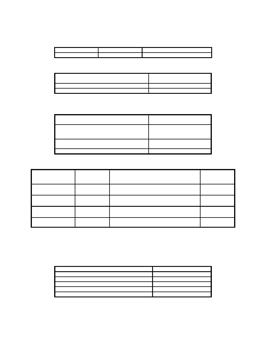
Table 19
Removable Stop Bolt Maximum Spacing for Low Threat Severity Level
Space
Maximum Spacing,
inch (mm)
Frame Corner to Bolt
9 (230)
Between Adjacent Bolts
18 (460)
Table 20
Minimum Wall Thicknesses for Low Threat Severity Level
Wall Construction
Minimum Wall Thickness
inch (mm)
Wood Frame
Refer to Table 1 for
details of wood frame
construction
Reinforced Grout-Filled Concrete
6 (150)
Block
Reinforced Concrete
4 (100)
Table 21
Minimum Glazing Specifications for Medium Threat Severity Level
Type
Minimum
Minimum Thickness,
Figure
Thickness,
inch (mm)
inch (mm)
Air Gap
1-3/4 (44)
Figure F-6
1/4 (6) LAMa AGb, 1/4 (6) AIR, 1-
1/8 (28) LAM POLYc
Extruded
2-1/8 (54)
Figure F-9
7/8 (22) LAM AG, 1 (25) IONOMERd,
Ionomer
3/32 (4) AG
Glass-Clad
15/16 (24)
Figure F-14
3/16 (5) SGe, 1/4 (6) AG, 3/8 (9)
Polycarbonate
LAM POLY
Laminated
1-1/4 (32)
1-1/4 (32) LAM POLY
Figure F-31
Polycarbonate
a
Laminated
b
Annealed glass
c
Polycarbonate
d
Extruded ionomer
e
Strengthened glass
Table 22
Minimum Frame Specification for Medium Threat Severity Level
Item
Size, inch
Mimimum
Frame Thickness
1/4 (6 mm) steel
Minimum
Removable Stop Thickness
3/16 (5 mm) steel
Minimum
Bite Depth
1 (25 mm)
Minimum
Glazing Rabbet Depth
1-1/4 (32 mm)
Maximum
Width Between Frame Members
42 (1.1 meter)
70
|
 |
|
|
||


