

Custom Search
|
|

|
||
 MIL-HDBK-1023/4
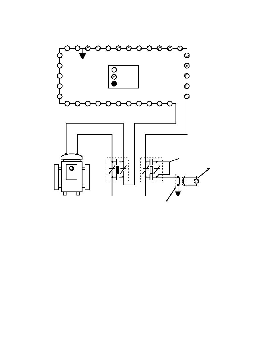
to dim, making the task of locating the ground fault much easier. Simply driving the circuit and
looking for the bright to dim transition in the lights will isolate the area of the ground.
= ON
= DIM
= OFF
S1-B
S1-A
JUMPER
45 W EDGE LIGHT
ON
REGULATOR
GROUND.
45 W ISOLATION
S1-A: TYPICAL INSTALLATION ON LOAD CIRCUIT - HANDLE INSTALLED.
S1-B: GROUND RETURN SWITCH WITH GROUND CURRENT INDICATING LIGHT -
HANDLE REMOVED.
CAUTION: OPERATE S1 HANDLES WITH LOAD DE-ENERGIZED.
Figure 25
Single Ground on Load Circuit - Intentional Ground Method
(3) Notice that the indicating light connected to the intentional ground is also dim.
The ground current indicating circuit provides the operator of the regulator with a visual
indication of current flow through the intentional ground, as well as a pass/fail test for the
presence of a significant ground on the load, a significant ground being a ground fault of low
enough resistance to conduct enough current to light the indicating lamp.
88
|
 |
|
|
||


