

Custom Search
|
|

|
||
 MIL-HDBK-1023/4
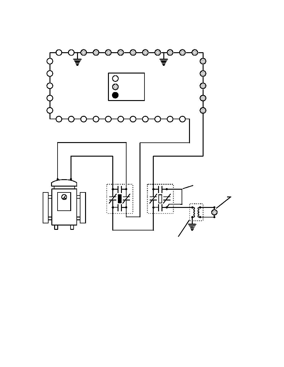
(4) Figure 26 illustrates the results of multiple grounds on the load circuit with an
intentional ground connected to the load.
= ON
= DIM
= OFF
S1-B
S1-A
JUMPER
45 W EDGE LIGHT
ON
REGULATOR
GROUND.
45 W ISOLATION
S1-A: TYPICAL INSTALLATION ON LOAD CIRCUIT - HANDLE INSTALLED.
S1-B: INTENTIONAL GROUND SWITCH WITH GROUND CURRENT INDICATING LIGHT -
HANDLE REMOVED
CAUTION: OPERATE S1 HANDLES WITH LOAD DE-ENERGIZED
Figure 26
Two Grounds on Load Circuit Intentional Ground Method
(5) As Figure 26 shows, the ground fault to the right might not be easy to find as
the fault on the left, but fixing the ground fault on the left side of the load will shift the light
intensity transition over to the fault on the right and finding its location will be easy.
89
|
 |
|
|
||


