

Custom Search
|
|

|
||
 The design allows for the rejection of denied vehicles after the vehicle identification
and personnel identification points when operated with automated equipment. The
layout supports rejection of the largest vehicles (AASHTO WB-15m (WB-50)) with one
turning movement from the truck/visitor lane and standard POV from the remaining
lanes. Rejection of a vehicle from the reversible lane will require a three-point turn,
which is facilitated by a turnout in the roadway.
The entire entry control facility is surrounded by a passive vehicle barrier system,
which provides total containment of the vehicles until the active vehicle barriers are
reached. Active vehicle barriers are provided in both the inbound and outbound lanes
The electrical design incorporates spare duct bank and conduit to facilitate future
installation of automated access control systems.
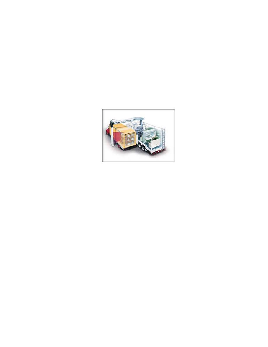
Figure 6.1 Mobile X-Ray Inspection Equipment
6.2 Variations and Alterations to the Prototype
Due to the wide array of potential design constraints and considerations it is impossible to
handle all situations with a typical entry control facility design. As discussed in Chapter 5,
there are four basic design scenarios that encompass possible design solutions. Ref. 2
identified several baseline concepts that encompass many commonly encountered design
situations. These concepts are based on assumptions concerning the relative size of approach
and response zones (Design Scenarios 1-4). The conceptual layout provided for the
prototype is based on Design Scenario 1. The prototype is intended to illustrate the desirable
elements of an ECF. These elements must be combined in an appropriate manner for each
ECF.
43
|
 |
|
|
||


