

Custom Search
|
|

|
||
 MIL-HDBK-232A
5.4.3.3 Patch panels. Patch panels are used to substitute equipment or
lines when failures occur. Patch panels must be designed to allow all
required signals to be transferred from one equipment or line to another
equipment or line with the least effort. Each patching position must have
sufficient contacts to transfer not only the signal lines, but all returns
(see figure 29). The Designer should consider all signals to be balanced and
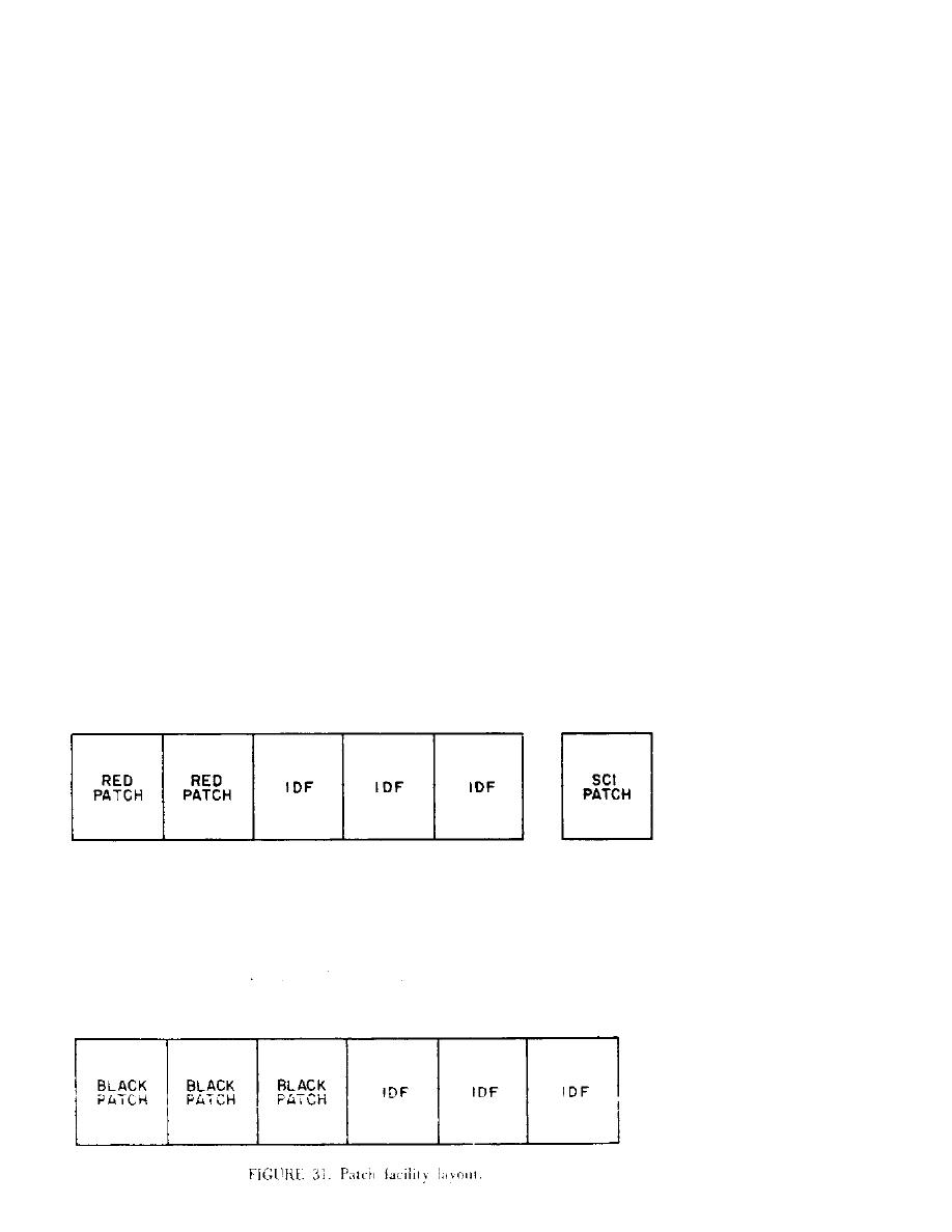
provide the appropriate patching. For RED patching where like items of
equipment serve different communities of security, separate patching for each
community is required. These panels must be physically separated to prevent
patching from one to another (see figure 31). It is preferred that different
patching media be used (see figure 32). If separation and physical
difference cannot be used, then dissimilar wiring of each patch position may
be used (see figure 33). The dissimilar wiring should take a form that
effectively inhibits circuit operation when an operational mispatch is made.
For instance, if a signal line used to initiate a crypto-resynchronization
were to be reversed with a clock line, should a mispatch occur, the
crypto-equipment would be continually in resynchronize mode, but could not
operate due to the lack of the clock signal. Dissimilar wiring should be
used only if other methods cannot be used. Small facilities should use
crossover switches in lieu of patch panels (see figures 34 and 35).
5.4.3.4 Equipment terminations. Equipment terminations present the designer
and installer with a variety of possible termination techniques. Termination
may be on barrier strips with crimp connectors, wire wrapped to backplane
pins, fanned and soldered to printed wire boards, or on wide variety of
connector plugs. However, some general rules can be applied. The designer
and installer must be aware of typical interface schemes in order to
understand the termination scheme and take actions to overcome the
shortcomings of particular interfaces. Digital interface schemes can be
classed as follows: balanced voltage digital signaling, unbalanced voltage
digital signaling (see figure 36), and loop current (see figure 37).
|
 |
|
|
||


