
Custom Search
|
|

|
||
 MIL-HDBK-419A
circuit loop in terms of the current flowing in a nearby conductor parallel to the sides of the loop. Substituting
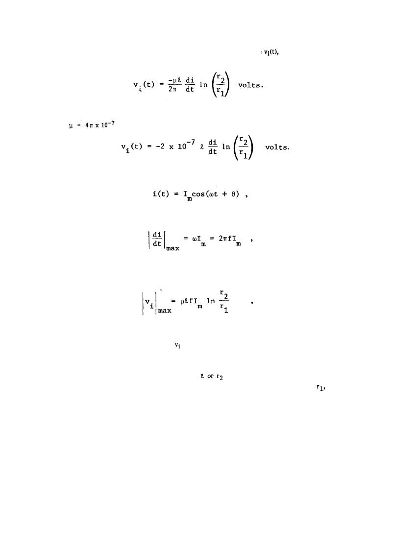
the total magnetic flux from Equation 6-5 into Equation 6-3 gives the voltage
induced in the circuit loop
(6-6)
In free space,
henrys/meter, and Equation 6-6 reduces to
(6-7)
If the interference current in the nearby conductor is sinusoidal, i.e.,
(6-8)
then the maximum value of di/dt is
(6-9)
and the maximum value of the induced voltage in Equation 6-6 is
(6-10)
where f is the frequency of i(t).
In Equations 6-6 and 6-7, the induced voltage
(t) in a circuit loop with sides parallel to a current i(t) is
expressed in terms of the dimensions of the loop, the distance of the loop from the current i(t) and time rate of
change of i(t). As can be seen from these equations, the induced voltage in a susceptible circuit loop increases
with an increase in the loop area (either an increase in
or both), the frequency, f, or the time rate of
change, di/dt, of the interfering sources, and increases with a decrease in the distance,
between the
interfering source and the loop.
The preceding equations indicate that the induced voltage is independent of the impedance of the susceptible
circuit loop; i.e., the amplitude of the induced voltage is the same in a high impedance circuit as it is in a low
impedance circuit. The desired signal voltages in low impedance circuits, however, are generally much lower
than in high impedance circuits. Therefore, in low impedance circuits the induced voltage can be high relative
to the signal voltage and thus more likely to produce significant interference in the circuit load. In high
impedance circuits the same induced voltage may be small compared to the circuit signal voltages and thus not
create any problems. For these reasons, low impedance circuits are usually more susceptible to inductive
coupling than are high impedance circuits.
6-10
|
 |
|
 |
||