
Custom Search
|
|

|
||
 MIL-HDBK-419A
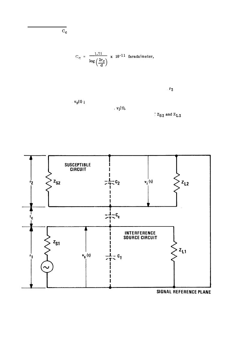
6.2.2.3 Capacitive Coupling. When signal conductors of two circuits are near each other as shown in
Figure 6-9, a capacitance,
exists between the conductors. The value of this capacitance is a function of the
where rc is the distance between the two lines and d is the diameter of the wires. In a similar manner, a
capacitance exists between each signal line and its return. If the signal line is parallel to its return, these
(see Figure 6-9).
The interference source voltage,
two signal conductors and develops an induced voltage,
in the susceptible circuit. The equivalent circuit
for Figure 6-9 is given in Figure 6-10(a) where the parallel combination of
has been replaced by
the equivalent impedance
(6-12)
Figure 6-9. Illustration of Capacitive Coupling
6-11
|
 |
|
 |
||