

Custom Search
|
|

|
||
 MIL-HDBK-419A
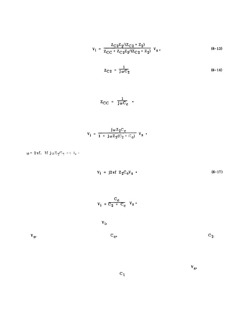
and time-varying voltages have been replaced by their ac steady state phasors. The induced voltage (ac steady
state assumed) in the susceptible circuit is
where
and
(6-15)
Substitution of Equations 6-14 and 6-15 into Equation 6-13 yields
(6-16)
which is generally true at lower frequencies, the equivalent circuit of Figure
where
6-10(b) is applicable and
At higher frequencies, the equivalent circuit of Figure 6-10(c) is applicable and
(6-18)
These equations illustrate the induced voltage,
which is capacitively coupled into a susceptible signal circuit
from a nearby signal conductor, is dependent on the amplitude and frequency of the interference source
the stray capacitance in the susceptible circuit,
and
voltage,
the values of the coupling capacitance,
on the magnitude of the impedance of the susceptible circuit. At low frequencies, Equation 6-17 indicates that
the induced voltage increases with either an increase in the coupling capacitance or an increase in the
impedance of the susceptible loop. Similarly, at high frequencies the induced voltage as given in Equation 6-18
increases with either an increase in the coupling capacitance or a decrease in the stray capacitance of the
susceptible circuit. It should also be noted that the value of the interference source voltage,
depends upon
the stray capacitance in the interference source circuit,
in Figure 6-9.
6-12
|
 |
|
|
||


