

Custom Search
|
|

|
||
 MIL-HDBK-419A
Table 1-28
Attenuation Correction Factors for Reinforcing Steel (1-14)
Bar Diameter
Bar Spacing
No. of Courses
Correction Factor
(in.)
(in.)
(dB)
Single
2.257
12
+5
Single
0
1.692
14
Single
1.000
18
-6
2.257
20
Double
+8.5
1.692
14
Double
+13
1.000
Double
16
+5
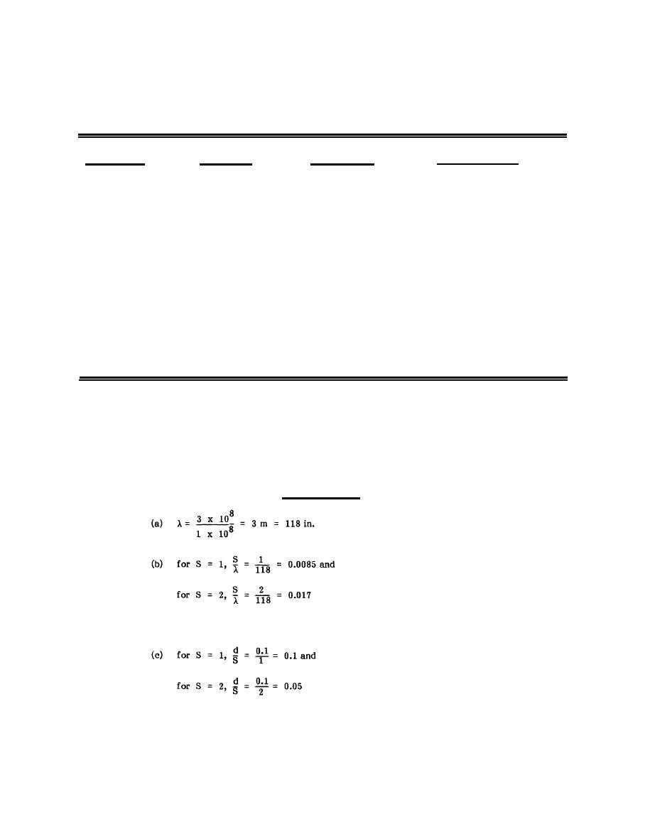
(3) Use Figure 1-84 to determine the relative attenuation of rebar (and other wire mesh or grid)
to higher frequency electric fields and plane waves. To use this figure, first calculate the ratio of the wire (or
bar) diameter, d, to the wire spacing, S. Then determine the ratio of S to the wavelength, λ, at the frequency,
f, of interest (λ in meters = 3 x 10⁸ divided by f in hertz). For example, determine the shielding effectiveness
at 100 MHz of a 1" x 2" grid made of No. 10 AWG (0.1" diameter) wire.
Calculation Steps
depending upon the polarization of the incident wave.
1-157
|
 |
|
|
||


