

Custom Search
|
|

|
||
 MIL-HDBK-419A
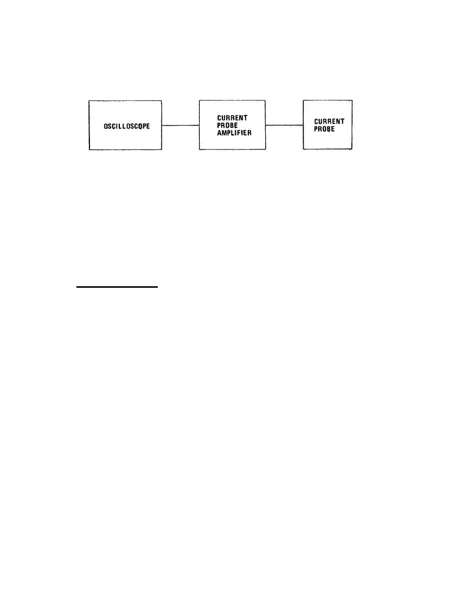
Figure 2-13. Test Setup for Stray Current Measurements
(6) Let the camera shutter remain open for five minutes or until the oscilloscope is triggered,
whichever occurs first. (Longer sampling periods may be used if desired.)
(7)
Record pertinent information on the test photograph,
(8) If a spectrum analyzer plug-in is available for the oscilloscope, perform the current
measurements in the frequency domain as well as the time domain. (Frequency domain measurements can be of
great assistance in identifying the source of interference currents.1
2.2.2.3.3 Differential Noise Voltage.
a.
Equipment Required.
(1)
Oscilloscope with time and frequency domain plug-ins.
(2) Oscilloscope camera.
(3) Isolation transformer.
(4)
Required lengths of shielded cable.
Equipment Setup and Test Procedure.
b.
(1) Set up the equipment as shown in Figure 2-14. Note that the signal probe and the "ground"
reference probe are connected to each of the two points between which the voltage differential is desired.
(2) After an adequate warm-up time, photograph the ambient noise level in both time and
frequency domains.
(3) If transient data is required, proceed as indicated in steps four through seven in Section
2.2.2.3.2, above,
2-22
|
 |
|
|
||


