

Custom Search
|
|

|
||
 TM 5-684/NAVFAC MO-200/AFJMAN 32-1082
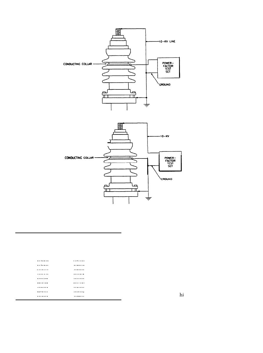
HOT-COLLAR TEST
,
L
I
N
E
.
COLD-COLLAR TEST
Figure 3-2. Connections for hot- and cold-collar tests
Table 3-4. Insulation resistance tests on electrical apparatus
(1) Readings taken on a number of similar
and systems1
bushings at the same time.
(2) A series of readings taken on the same
Recommended
bushings at different times.
minimum
c. Test conditions. It is essential that suitable
insulation
Maximum voltage
Minimum test
resistance in
conditions be maintained during tests.
rating of equipment
voltage, dc
megohms
(1) Bushings cannot be checked while con-
250 volts
500 Volts
25
nected to the windings of transformers.
100
600 volts
1,000 Volts
(2) Bushings must be dry and warm enough to
2,500 Volts
5,000 volts
1,000
prevent the condensation of moisture from the at-
8,000 volts
2,500 Volts
2,000
15,000 volts
2,500 Volts
5,000
mosphere.
25,000 volts
5,000 Volts
20,000
(3) The weath er should be reasonably clear and
35,000 volts
15,000 Volts
100,000
the relative humidity less than 80 percent.
46,000 volts
15,000 Volts
100,000
(4) Record the bushing temperature at time of
15,000 Volts
69,000 volts
100,000
test.
1This
table is reproduced from MTS-1993.
(5) Adjust resistance value to 68 degrees F (20
degrees C).
3-13
|
 |
|
|
||


