

Custom Search
|
|

|
||
 TM 5-684/NAVFAC MO-200/AFJMAN 32-1082
441. Overhead line conductor splices.
not be salvaged. A compression connector may be
used only for the size of conductor for which it is
A splice is generally considered to be an end-to-end
made. Neither the connector nor the conductor
connection. It must be able to transmit the maxi-
should be altered to fit a conductor for which the
mum electrical load without undue heating and
connector was not designed. Several types of com-
should usually develop the full mechanical strength
pression sleeve splices are available:
of the conductors. Because of different characteris-
(1) Single sleeve. This splice is used for copper,
tics of copper and aluminum, connectors must be
suitable for the specific materials of the conductors
copper-clad, aluminum, and aluminum-clad conduc-
joined. Materials such as fluxes, inhibitors, and
tors, as shown in figure 4-12. A sealant port and set
compounds should be of a type which will not ad-
screw or plug is provided for injecting filler paste
versely affect the conductors. See chapter 1, section
before compressing the splicing sleeve with a
III. Compression and automatic-type splices cor-
hydraulically-powered compression tool. Some con-
rectly join together conductors in tension and pro-
nectors may have a factory-applied sealant.
vide the strength and electrical conductivity re-
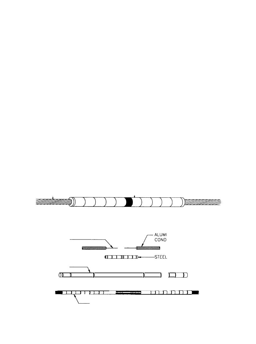
(2) Double-sleeue. This splice is used for ACSR
quired. Twist sleeve splices are no longer in use
conductors. In this type a steel sleeve is used to join
because they do not develop the strength of other
the steel support stand, and an aluminum sleeve is
connectors. Implosive-compression connectors are
used to join the aluminum conductors, as shown in
not recommended for use by facility personnel, as
figure 4-13. Both sleeves need to be compressed,
special training is required. Conductor connections
and the aluminum strands need to be cut back from
should be kept to a minimum. Keep splices in
the steel core.
transmission-line conductors at least 50 feet (15
(3) Single-sleeve and internal gripping unit.
meters) or more from dead-end connections. Do not
This splice is used for ACSR. A gripping unit pro-
make splices in lines crossing over railroads, rivers,
vides continuity for the steel core of the conductors
canals, or freeways. Also try to avoid splices in
being spliced and provides the required strength for
spans crossing over communications circuits or elec-
the tension applied. The splice requires only one die
tric transmission and distribution lines.
a. Compression sleeve splice. Compression sleeves
in the compression tool, as the gripping unit re-
provide full strength and conductivity and will pro-
places the double-sleeve's inner sleeve compressed
duce the most trouble-free connection, but they can-
on the steel core.
r
r
CONDUCTOR
SLEEVE
Figure 4-12. Single-sleeve compression splice (Courtesy of BURNDY Electrical)
STEEL SUPPORT
NUM
STRAND
UCTOR
SLEEVE
ALUMINUM
SLEEVE
D
D
DD
VIEW AFTER INSTALLATION
Figure 4-13. Double-sleeve compression splice (Courtesy of BURNDY Electrical)
4-19
|
 |
|
|
||


