

Custom Search
|
|

|
||
 TM 5-684/NAVFAC MO-200/AFJMAN 32-1082
4-42. Overhead line connections.
(4) Secondary and service cables. Secondary
and service cables can be spliced with bare or insu-
Tap, jump, loop and secondary dead-end connec-
lated compression connectors in a similar manner.
tions are generally considered to be tee connections.
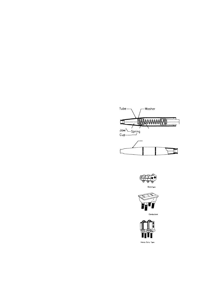
b. Automatic tension splice. Automatic tension or
The connection must be able to transmit the re-
line splices with their single-bore sleeve as shown in
quired load current and have sufficient mechanical
figure 4-14 can only be used in any span where the
strength to support the connection and the con-
wires are continually in tension. To install, force the
nected conductors. In general, the connection
gripping teeth of the splice jaws onto the conductor
should be suitable for installation without having to
by imposing several severe jerks on the conductor or
be joined to the main tension line conductor. Con-
by pulling on the conductors to obtain a tension
nectors are available in a wide range of sizes for
exceeding 15 percent of the rated breaking strength
connecting copper to copper, aluminum to alumi-
of the conductor. If an attempt is made to withdraw
num, and copper to aluminum. It is essential that
the conductor, the splice jaws will clamp down on
the proper size and type of connector be used. For
the conductor because of a taper in the bore of the
tapping conductors over No. 2/O AWG in size, a
sleeve and on the jaws. The tension causes a wedg-
stirrup should be used on each conductor, with a hot
ing action which increases with the pull applied on
line clamp, to avoid "burndown" of the feederline in
the conductor. A loss of tension could cause the jaws
to release their grip and allow the conductor to drop
the event of a heavy fault or "heated up" tap connec-
out. This type of splice is used where service must
tor.
be restored quickly and is especially suited for live-
line splicing.
(1) Care. Automatic line splices must be clean,
as any contaminants will impair the proper opera-
tion of the internal jaws. Splices that have lost their
original protective wrapping should be carefully in-
spected for any dirt. During installation and until
the conductor reaches its final installed tension,
automatic line splices should not be dragged
Cartridge Assembly
through any element that could cause soiling. Any
splice with a deformed or dented barrel will inter-
fere with the proper seating of the internal jaws and
should not be used.
(2) Unsuitable Locations. Splices should not be
Figure 4-14. Automatic tension splice
installed within 12 inches (300 millimeters) of a tie
wire or armor rod. Splices cannot be used in taps
and jumpers which have no tension, on conductors
of dissimilar metals, or where there is severe vibra-
tion.
c. Clamp splices. Bolted-type connectors as
Normal
shown in figure 4-15 are not recommended for
wires under tension. Most clamps are designed
primarily for conductivity and may not provide
the required strength unless two or more are
used.
d. Wires of different sizes. When the conductor
For Flexible
size changes at a pole, special construction is usu-
ally necessary for conductor attachment. Some au-
tomatic line splices are available for use where this
size difference is not great; but pins, insulators, and
the line ties must be strong enough to hold the
difference in tension between the two conductors.
Under the worst loading conditions, when this ten-
sion difference exceeds 500 pounds (225 kilograms),
automatic line splices are not recommended.
Figure 4-15. Clamp connectors (Courtesy of BURNDY Electrical)
4-20
|
 |
|
|
||


