
Custom Search
|
|

|
||
 TM 5-684/NAVFAC MO-2OO/AFJMAN 32-1082
a. Split-bolt connectors. Split-bolt connectors
(1) Burning of the main conductor at the con-
(bugs) are used extensively on lower voltage cir-
tact due to looseness and high resistance;
cuits, utilizing No. 2 AWG or smaller copper conduc-
(2) Difficulty of removal due to freezing of the
tors, and are also available in larger sizes. Where
bolt in the body. The clamp should be located where
vibration or twisting occurs, the contact pressure of
vibration and flexing of the tap wire will be a mini-
a split-bolt connector will relax and may cause arc-
mum. To prevent burning from damaging and pos-
ing, resulting in a burned-down conductor. Spacing
sibly dropping the main conductor, a hot line clamp
two connectors about 6 inches (150 millimeters)
should not be attached directly to the main conduc-
apart will reduce this hazard. Never reuse a split-
tor except in a nontension loop. The best method is
to attach a suitable stirrup, either clamp or com-
bolt connector, as it has probably been damaged in
removal. Any bending or forming of the conductors
pression type, and apply the hot line clamp to the
should be made before final tightening of the con-
stirrup. In this way, any burning at contact or arc-
nector. Never use split-bolt or similar type of con-
ing during removal will burn the stirrup and not
nectors for medium-voltage splices under tension.
damage the main conductor. Hot line clamps can be
b. Bolted connectors. Bolted connectors are of
applied over armor, if the contact between conduc-
tor and armor is thoroughly cleaned first. The prob-
various sizes and types, using one or more straight
lem of freezing threads is a matter of design, and
or U bolts to provide the contact pressure. The con-
ductors may make contact with each other or they
the more modern hot line clamps are much less
may be separated by spacers on the body of the
likely to have this trouble. Any hot line clamp that
clamp. Any bending or forming of the conductors
is not in good condition should be discarded.
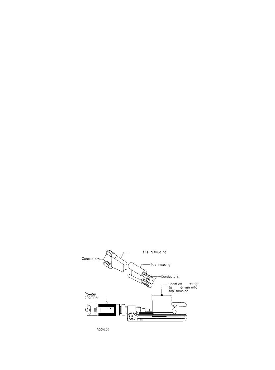
e. Internally-fired taps. Internally-fired taps are
should be completed before the final tightening of
the connector.
used for a tee connection on transmission and dis-
c. Compression tap connectors. Compression-type
tribution conductors of both copper and aluminum.
tap connectors are available in such forms as T, L,
The tap housing is made of a suitable alloy, tapered
and parallel. To fit over the main conductor without
at the ends where the conductors enter. The appli-
having to cut it, the connector has a U-shaped open-
cation tool as shown in figure 4-16 contains a high-
ing. This connection is not as strong as the full
strength steel powder chamber that is loaded with a
round splice connection, but if properly applied it is
fast-burning propellant charge contained in a poly-
superior to any bolted connection. The connector is
ethylene cartridge. A simple hammer blow deto-
nates the cartridge. Igniting the charge creates in-
not reusable, and removal requires cutting the main
stantaneous high pressure in the chamber. This
conductor. If the tap is no longer needed, the tap
wire may be cut off and the connector left on the
pressure drives cylindrical sets of wedge-shaped
serrated aluminum jaws (into which the conductor
main conductor.
d. Hot line clamps. Hot line clamps are used for
ends have been inserted) at high velocity into the
tapered ends of the housing. The jaws clamp and
either temporary or permanent connections in
lock the conductor ends in position, providing the
places where it is necessary or convenient to use hot
required holding strength and establishing a low-
sticks, and where the connection must be occasion-
ally opened. Hot line clamps are prone to two types
resistant current path across the housing. If cor-
of trouble:
rectly operated, a locking tab will verify the wedge
Wedge
of
be
\
on
tool-
Figure 4-l 6. Internally-fired tap components
4-21
|
 |
|
 |
||