

Custom Search
|
|

|
||
 TM 5-684/NAVFAC MO-200/AFJMAN 32-1082
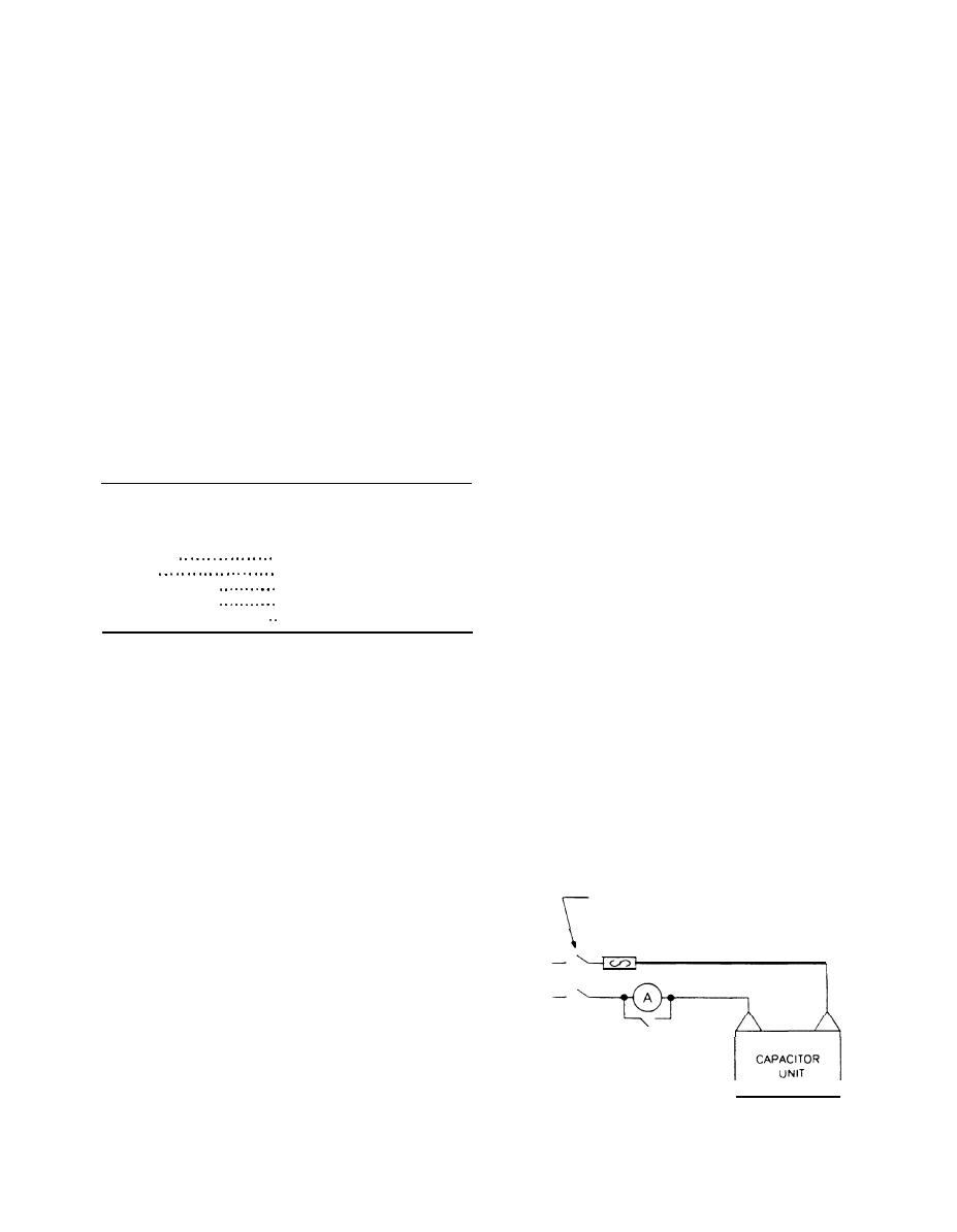
(1) Terminal-to-terminal voltage test. The pur-
b. After being in service tests. These tests are only
pose of this test is to determine whether a capacitor
necessary in determining the operating condition of
unit is functioning in accordance with its rating.
a power capacitor after exposure to possible damage
or other trouble indications. The dielectric strength
Capacitor units found to be internally defective are
may be measured by applying the same voltage as
more economically replaced than repaired.
given for the before service test. The capacitance
(a) Procedure. With the capacitor unit insu-
can be determined by applying a known voltage and
lated from ground, apply a terminal-to-terminal
frequency of a good wave shape. Short-circuited or
voltage equal to the rated capacitor voltage, in ac-
open-circuited capacitors will be indicated by this
cordance with figure 13-l. Voltage should be ap-
test. Tests for terminal resistance and liquid tight-
plied for one minute with the test circuit fused.
ness may also be desirable, as covered in later para-
Fuse rating should be that recommended for the
graphs.
capacitor, or if that size is not readily available, one
c. Capacitor bank automatic switching. Switched
rated twice the normal load current. Measure the
capacitor banks should be inspected for proper op-
voltage and current. The ammeter should be pro-
eration every year. The maintenance schedule given
vided with a short circuiting switch. The switch
in table 13-2 is based on the indicated types of
should be opened only after it has been determined
on-off controls. For oil switches, open and close op-
that no short circuit exists.
erations between maintenance periods should not
(b) Interpretation. Blowing of the fuse indi-
exceed 2,500.
cates a short-circuited capacitor. Absence of current
indicates an open-circuited capacitor. Good capaci-
Table 13-2. Capacitor bank oil switch maintenance1
tors should have current readings of 100 to 115
percent of rated value, with the case and internal
Maintenance
temperature at 25 degrees C. Current readings
schedule,
years
above 115 percent of rated current may indicate an
Type of control
internal short or the presence of harmonics in the
3
Time clock.
test voltage. If waveform of the test voltage is sus-
3
Voltage.
5
pect, the test should be repeated using an alternate
Dual temperature.
8
Temperature only.
source of electric power.
8
Time clock and temperature
(2) Terminal-to-case insulation test. The pur-
pose of this test is to determine the adequacy of the
From "The Lineman's and Cableman's Handbook" by Kurtz and
Shoemaker, copyright 1992 by McGraw-Hill, Inc., used with the
insulation to ground of a given capacitor unit. This
permission of McGraw Hill, Inc.
test may be applied to two bushing, single-phase
capacitor units, but not to capacitor units where the
13-13. Terminal tests of power capacitors.
case is used as a terminal.
Terminal tests may be those measuring resistance,
(a) Procedure. With the capacitor unit insu-
as recommended by ANSI/IEEE 18, or may be
lated from ground, apply a voltage equal to twice
handbook-recommended insulation or voltage tests.
rated voltage between case and terminals (all termi-
a. ANSI/IEEE 18 resistance tests. Two-bushing
nals connected together) in accordance with figure
capacitors can be tested to determine whether their
13-2. Voltage should be applied for one minute,
insulation resistance (in reference to terminal-to-
with the test circuit fused and containing sufficient
terminal or terminal-to-case) is in agreement with a
impedance to limit the current, should the capacitor
value recommended by the manufacturer. When an
under test be shorted.
internal discharge resistor is present, however, the
reading obtained will be that of the discharge resis-
SWITCH OR
CIRCUIT BREAKER
tor. This is much lower than the dielectric resis-
tance, which may also need to be obtained from the
FUSE
manufacturer. This testing will indicate whether
the internal discharge resistor is operable. Remem-
ber, that the internal discharge device provided in a
capacitor is not a substitute for the recommended
practice of manually discharging the residual stored
POWER SOURCE
charge before working on a capacitor.
RATED VOLTAGE
b. Handbook tests. These are not standard indus-
AN0 FREQUENCY
try tests, but have been recommended by facility
engineers as a method of determining the capacitor
condition.
Figure 13-1. Terminal-to-terminal voltage test circuit.
13-3
|
 |
|
|
||


