

Custom Search
|
|

|
||
 13-14. Leak tests of power capacitors.
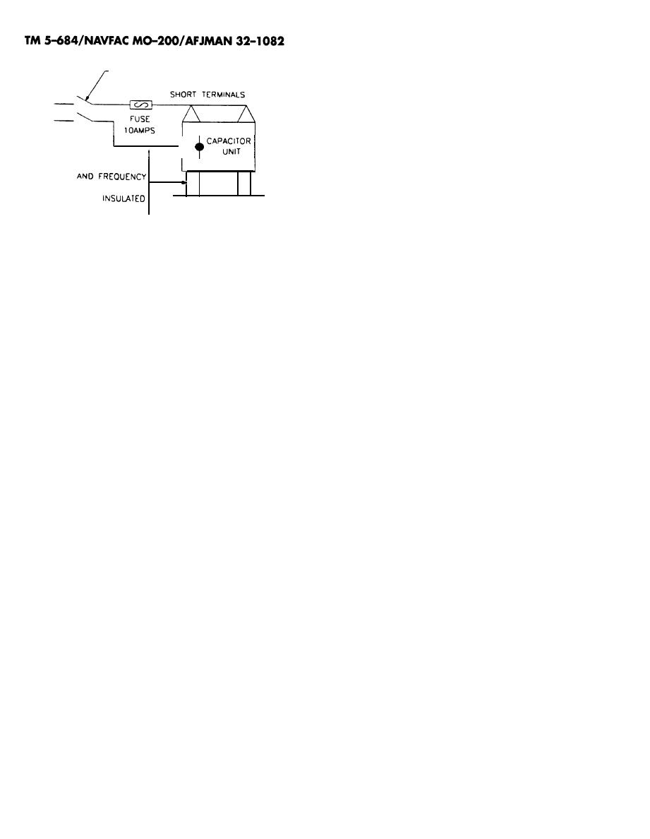
SWITCH OR
CIRCUIT BREAKER
Capacitor cases do develop leaks. Since capacitor
installations are normally made up of a number of
individual units, it is sometimes difficult to ascer-
tain the unit or units that are leaking.
a. Procedure. If the unit at fault cannot be found
MAXIMUM
b y visual inspection, the suspected capaci-
POWER SOURCE
tors should be removed; thoroughly cleaned; and
RATED VOLTAGE
placed in an oven for a minimum of 4 hours. The
temperature of the capacitor case should not be
CAPACITOR
CASE
allowed to exceed the manufacturer's recommenda-
FROM GROUND
tions.
b. Interpretation. Place the capacitors horizon-
Figure 13-2. Terminal-to-case insulation test circuit
tally on a sheet of clean paper (brown wrapping
paper is suggested) with the suspected point of leak-
(b) Interpretation. Failure to pass this test
age on the bottom. Leaky capacitors should be re-
indicates an internal flashover and the capacitor
placed.
should be replaced.
13-4
|
 |
|
|
||


