
Custom Search
|
|

|
||
 3.6.1 End and Gland Seals. S e a l s are used to prevent water infiltration
where the conduit runs through walls, as at manholes and entrances to
End seals are used when there is no longitudinal movement of the
buildings.
p i p e , as at terminal ends of conduits inside manholes, pits, or building
w a l l s . End seals consist of a steel bulkhead plate welded to the pipe and
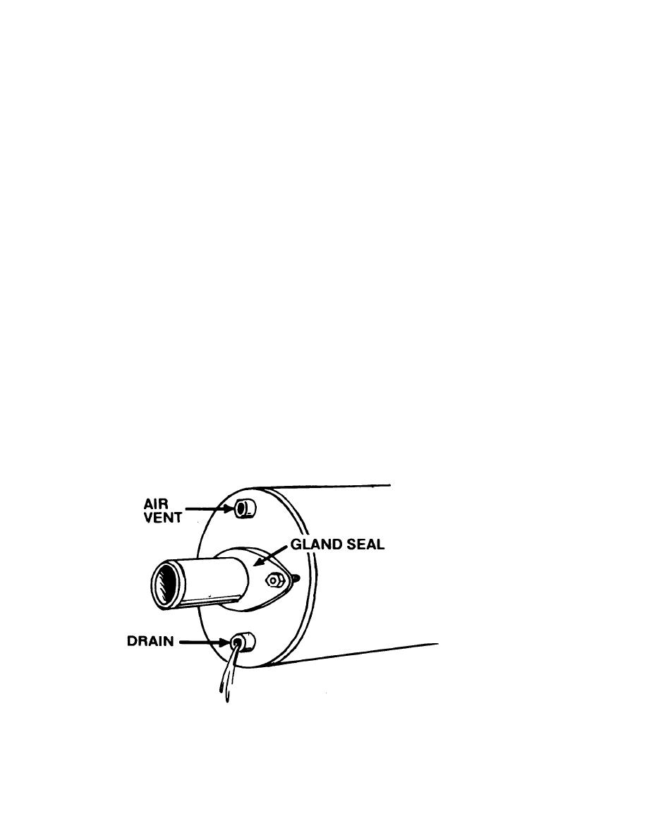
Figure 3-2 illustrates an end seal. When the pipes can have
conduit.
l o n g i t u d i n a l movement, gland seals are used to prevent water infiltration.
Gland seals consist of a packed stuffing box and gland follower mounted on a
steel plate welded to end of conduit. End seals or gland seals are equipped
w i t h drain and vent openings located diametrically opposite on the vertical
c e n t e r l i n e of the seal. T e l l t a l e vents, located at the top of the seal, are
never less than 1 inch in diameter and must provide a free passage to the
airspace between the insulation and the conduit walls (refer to paragraphs
3 . 6 . 2 and 3.6.3). Drain connections (l-inch minimum diameter) are located at
the bottom of the seal.
3 . 6 . 2 Type A-1, Cast Iron Conduits. T h e s e units are prefabricated at the
f a c t o r y in standard length sections. T h e y consist of pipe(s) individually
covered with premolded or preformed pipe insulation of proper thickness,
( r e f e r to chapter 7), and a cast iron conduit casing. T h e insulated pipe is
supported within the metallic casing in such a way that a continuous annular
space (l-inch minimum) is provided for the entire length of the system,
between the outer surface of the insulation and the inner surface of the
e x t e r i o r casing. This provides adequate continuous airspace for venting and
A n extension of bare pipe is left at each end of the section for
draining.
w e l d i n g in the field. A f t e r welding, joint closures are made by applying
i n s u l a t i o n to the pipe and then using a solid sleeve or mechanical joint for
t h e conduit. I n other types of installations the conduit is furnished with
flanged ends to make the joint closures. F i g u r e s 3-3 and 3-4 illustrate a
s o l i d sleeve joint and a standard mechanical joint, respectively. P i p i n g is
pitched by the slope of the trench bottom. Supports and anchors are designed
to permit complete drainage of the casing in place and to allow freedom of
airflow.
FIGURE 3-2.
Conduit End Seal
3-8
|
 |
|
 |
||