

Custom Search
|
|

|
||
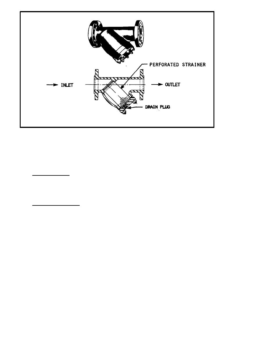 FIGURE 3-18.
Pipeline Strainer With Section View
pressure reducing and pressure regulating valves. Bypass valves should be of
the globe type to permit manual regulation, and they are usually half the size
of the pressure reducing or regulating valves.
2.6 Pressure Gauges. Pressure gauges should be installed on the high- and
low-pressure side of the pressure reducing station to facilitate supervision
of the operation.
3 INSTALLATION.
3.1 Two-Stage Reduction. When making a two-stage reduction, the size of the
pipe on the low-pressure side of the valve is usually increased to provide for
the expansion of steam. This permits a more uniform steam flow velocity. The
valves are sometimes separated by a distance of about 20 feet to reduce
excessive hunting action of the first valve. Usually, where the steam
distribution pressure exceeds 50 psi, the pressure reducing valve is installed
near the connection between the main distribution line and the consumer
system, followed by the pressure regulating valve and a relief valve.
D o u b l e - p o r t e d , pilot-operated valves should be installed for large capacities,
especially for inlet pressures above 125 psi. Because double-ported valves
will not shut off completely on no-load demand, single-seated valves must be
used for such service. Reducing valves should be selected to operate fairly
open, with ratings and reduction ratios as recommended by the manufacturer. A
strainer and condensate drain should be installed ahead of the pressure
reducing valve. When the reduction ratio is more than 15 to 1, the reducing
valve should be installed with increased outlet or expanding nozzle to provide
for the increased volume of steam resulting from the reduced pressure.
3-54
|
 |
|
|
||


