
Custom Search
|
|

|
||
 (c) Check operation of the automatic drain traps. When the air pressure
is too low for proper operation of the traps, open manual drain valves for
direct drainage of condensate.
(d) Relieve air pressure in secondary air receivers by opening manual
d r a i n valves. This will also permit draining moisture condensate and sediment
accumulated in the tanks.
(e) In underground systems, keep draining equipment in service to remove
any water that may infiltrate into the manholes.
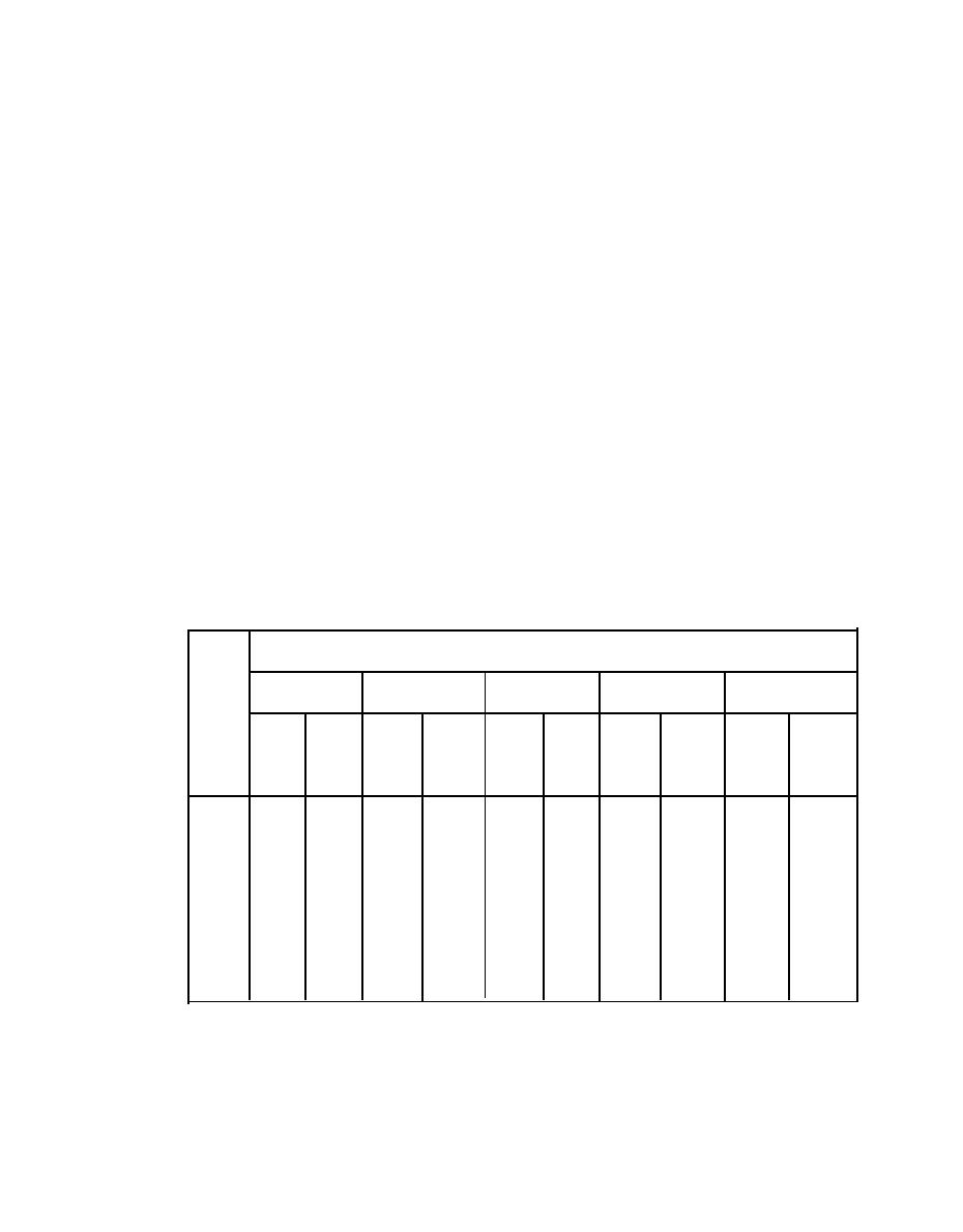
6 EMERGENCY PROCEDURES. R e p a i r all piping leaks as soon as possible. Refer
to table 5-2 for a quick estimate of the amount and cost of air leaks. The
d e f e c t i v e line can be isolated for repairs by closing segregating valves.
Often the service can be maintained to affected customers through an alternate
route by means of a loop closure.
7 CASUALTY PLANNING. M a k e certain operators are familiar with location and
arrangement of piping systems, v a l v e s , associated equipment, and controls. A
map of the area served, showing the location of the distribution piping,
equipment, and consumers, is very useful and should be available to
o p e r a t o r s . Give operators definite instructions on emergency procedures.
S c h e d u l e periodic practice fire drills, inspections, and other emergency
procedure tests. T r a i n all opertors in the use of available fire fighting and
emergency draining equipment.
Amount and Cost of Air Leaks1
TABLE 5-2.
Size of Hole (inches)
1/4
1/8
1/16
1 /32
1 /64
Cost
Air
Cost
Cost
Air
Cost
Air
Air
Air
Cost
Air
Per
Per
Losses
P e r Losses
Press.
Losses
Per
Losses
Per
Losses
(psig)
(cfm)
Month
(cfm)
Month
(cfm)
Month
(cfm)
Month
(cfm)
Month
$
$
$
$
$
815.00
9.42 203.50
37.8
50
0.146
3.15
0.594
12.80
2.37
51.00
60 0.169 3.65 0.682
14.75
2.73 59.00 10.9 235.50 43.5 940.00
70
0.192
4.15
0.773
16.70
3.09
65.50
12.3
265.50
49.4
1,065.00
80
0.214
4.60
0.864
18.65
3.46
74.50
13.8
298.00
55.2
1,190.00
90
0.237
5.10
0.955
20.60
3.81
82.00
15.3
330.50
61.1
1,330.00
100
0.260
5.60
1.05
22.70
4.19
90.50
16.8
363.00
66.9
1,445.00
110
0.279
6.00
1.14
24.60
4.55
98.00
18.2
393.00
72.8
1,570.00
120
0.305
6.60
1.23
26.55
4.93
106.50
19.6
423.50
78.6
1,695.00
130
0.325
7.00
1.33
28.70
5.28
114.00
21.1
455.50
84.5
1,825.00
140
0.351
7.60
1.41
30.45
5.64
122.00
22.4
484.00
89.7
1,935.00
150
0.370
8.00
1.51
32.60
5.98
129.00
23.8
515.00
95.5
2,060.00
0.429
9.25
1.72
37.15
6.89
149.00
27.4
590.00
110.0
2,375.00
175
0.494
10.65
2.00
43.20
7.93
171.00
31.6
680.00
127.0
2,745.00
200
Costs assume a continuously pressurized system.
1Airflow is based on nozzle coefficient of 0.64.
5-15
|
 |
|
 |
||