
Custom Search
|
|

|
||
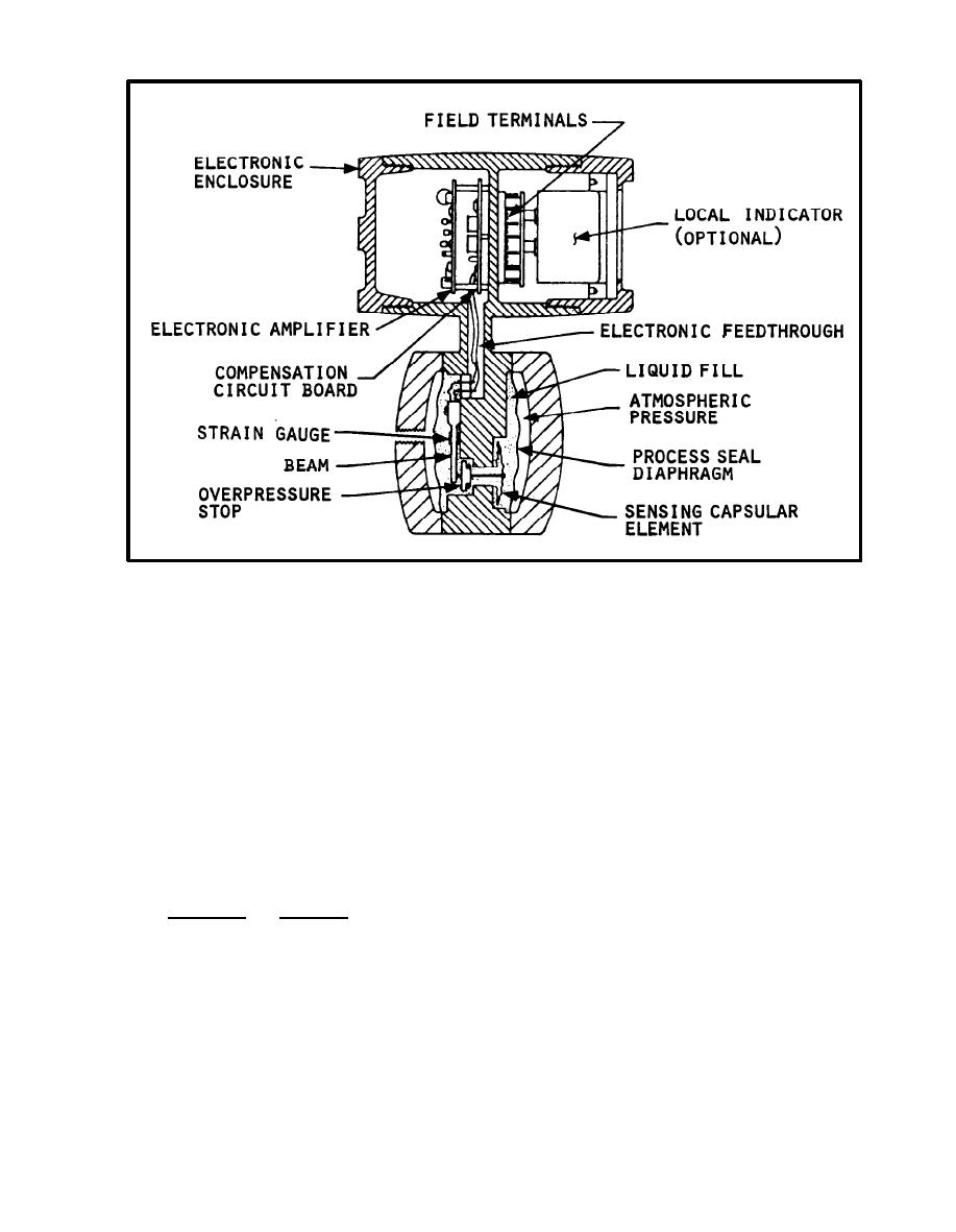
 FIGURE 6-10.
S e c t i o n View of Electronic Pressure Transmitter
t h i s closes the valve until the spring force balances the thrust exerted
through the valve stem by the diaphragm. T h e reverse is true for a decrease
i n t h e f l u i d c o n t r o l l e d p r e s s u r e . The controlled pressure can be adjusted by
changing the spring compression. When this type of valve is used for remote
c o n t r o l , s i g n a l air pressure from a pneumatic transmitter is applied in the
top chamber over the diaphragm.
6 . 1 . 2 Valve Seating Arrangements. V a l v e s can be of the single-seated type or
o f the balanced type. S i n g l e - s e a t e d valves are used for dead-end service,
where a pressure must be maintained during no-flow periods. T h i s type of
v a l v e can be closed tightly. B a l a n c e d valves require smaller forces to
o p e r a t e since the pressure acts on both sides of the disk. They do not close
t i g h t l y . S o m e valves are V-ported to provide throttling in the early stages
o f opening and closing.
6.2 Temperature Controls. T h e s e controls are used to maintain a substantially
c o n s t a n t temperature in one part of the system, regardless of load
P e r m i s s i b l e variations must be within the range of the
fluctuations.
equipment.
6.2.1 Temperature Control Components. A temperature control has three basic
elements which include a temperature sensing device (temperature bulb); a
r e g u l a t i n g valve, generally actuated by a bellows, to control the passage of
t h e heating or cooling fluid; and necessary capillary tubing connecting the
t e m p e r a t u r e bulb with the bellows. T h e temperature bulb, capillary tubing,
a n d bellows system are filled or partly filled with liquid, gas, or a
6-15
|
 |
|
 |
||