
Custom Search
|
|

|
||
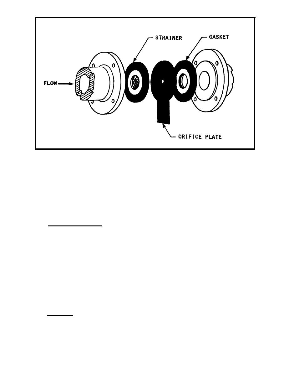
 FIGURE 8-8.
O r i f i c e Plate Trap
w i l l pass through the nozzle approximately 25 times faster than condensate,
but the denser condensate impedes the flow of the steam. Therefore, the steam
must push any condensate through the nozzle first before the steam can pass
through.
I f the line becomes clear of all condensate, steam will pass through
t h e nozzle, but the steam loss is negligible before more condensate forms to
be pushed through the nozzle. T h e nozzle trap is normally installed
d o w n s t r e a m of a strainer which prevents particles from clogging the orifice of
t h e nozzle. The venturi nozzle is palm size, has no moving parts, and comes
i n three standard pipe sizes: one-half, three-quarters, and one inch.
8 . 3 Piston Impulse Trap. T h e first thermodynamic operating trap is the
p i s t o n impulse style. ( R e f e r to figure 8-10.) The piston impulse style valve
l i f t s to expose a relatively large seat area for cool condensate. As the
condensate heats up and approaches steam temperature, some flows by the piston
opening around a disk on the piston valve and flashes into steam. The flash
steam at a pressure between Inlet and discharge is pushing against a
relatively large flange area on top of the disk and pushes the valve down and
closed.
Steam in the flash or control chamber prevents more steam from
e n t e r i n g the trap until it condenses. O n c e closed, the trap will not open
until steam in the control chamber cools and condenses and incoming condensate
blocks steam from flowing into the control chamber. When the steam in the
control chamber condenses, the pressure above the piston drops allowing the
valve to open. Air or noncondensable gas flows out the center vent hole in
t h e piston. I f blocked by dirt, the trap becomes airborne and nonfunction-
i n g . Normal trap failure may be open or closed.
8 . 4 D i s k T r a p . T h e disk trap consists of only three parts: body, cap, and
disk. The disk is the only moving part. (Refer to figure 8-11.) In
8-11
|
 |
|
 |
||