

Custom Search
|
|

|
||
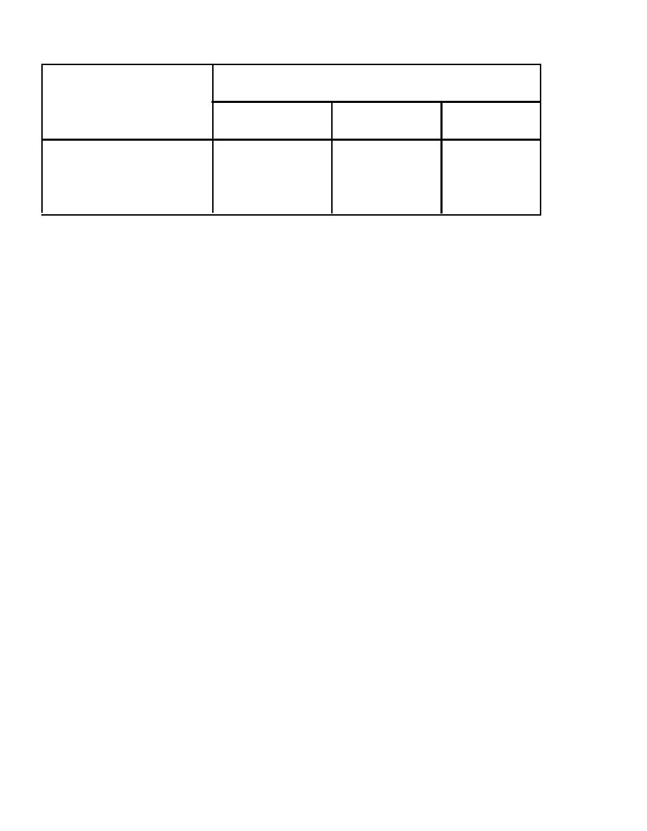 Percentage Reduction in Steam Trap Capacity
TABLE 8-6.
Back Pressure (percent of inlet pressure)
Inlet Pressure
75%
25%
50%
(psig)
18%
36%
10
5%
30%
3%
12%
30
28%
o
1 o%
100
o
23%
200
5%
t h e estimated condensate load, pressure conditions at the inlet and outlet,
a n d the configuration of the installation design. If the condensate load and
p r e s s u r e conditions can be accurately determined, the safety factor used can
b e low, which helps avoid oversizing. When experience with the steam system
a n d equipment, and thoughtful engineering of trap sizing are applied, safety
f a c t o r s in the range of 2:1 to 4:1 are adequate. When sizing from
m a n u f a c t u r e r s ' capacity ratings, make sure the ratings are based on flow of
c o n d e n s a t e at actual temperatures rather than theoretical rates or cold water
flow tests.
4 INSTALLATION GUIDELINES. The following guidelines can be used for optimum
l o c a t i o n and correct installation during system upgrade.
q Install unions on either side of the trap to a standard overall
d i m e n s i o n , to allow for easy servicing and replacement, and to provide
upstream and downstream service valves.
q A test discharge with valve is usually installed after the trap in
return condensate systems.
q Inlet and outlet piping to a trap should be equal to or larger than
t h e trap tappings. A l l unused inlet and outlet ports must be
plugged. W h e n using thread sealant tape, at least one thread is left
exposed on the outside to ensure that none of the tape is cut off on
t h e inside and carried into the trap.
q Since the use of cast iron traps is restricted to a working pressure
o f 250 psig or less, c o n s i d e r the use of nonrepairable stainless steel
t r a p s where applicable.
q Normally all lines slope in the direction of flow. Improper pitch may
result in pockets of condensate which contribute to damage by water
hammer. I f the return line slopes up, install a check valve upstream
of the trap.
q Install traps using the markings which indicate the direction of
f l o w . O r i e n t float, thermostatic, bucket, and disk traps to take full
a d v a n t a g e of gravity for effective operation.
8-24
|
 |
|
|
||


