

Custom Search
|
|

|
||
 CHAPTER 6.
VELOCITY METERS
Section 1. TURBINE AND FAN METERS
1. INTRODUCTION. Turbine and fan meters are inferential type meters. Both
determine actual flow by relating rotational speed of a moving element, which
acts as a turbine or fan, placed in the flow stream.
1.1 Operating Principles. Turbine and fan flowmeters use kinetic energy of a
flowing fluid to drive a turbine or fan which generate frequencies
proportional to flow rate. The rotational velocity of the rotating element
and the fluid velocity are linearly proportional over the working range of the
meter.
2. METER DESIGNS. All turbine and fan meters consist of a rotating element
or rotor. Rotor speed is linearly proportional to fluid velocity.
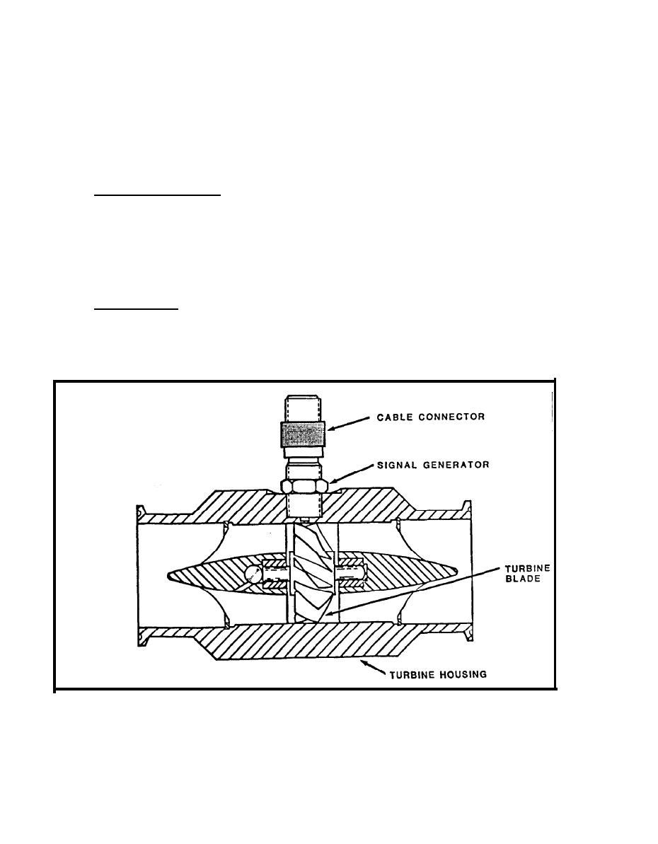
2.1 Turbine Meter. Turbine meters consist of a multiblade rotor mounted
within a pipe perpendicular to the fluid flow (Figure 6-l). The rotor spins
as the liquid passes through the blades. The rotational speed is a direct
function of flow rate and can be sensed by q agnetic pickup, photoelectric
cell, or gears.
FIGURE 6-1.
Turbine Meter
6-1
|
 |
|
|
||


