

Custom Search
|
|

|
||
 3.2.1 Current Transformer. Current transformers (CT) are designed to have
the primary winding connected in series with a circuit carrying current to be
measured or controlled. The secondary winding will then deliver a current
proportional to the line current for operation of meters, instruments, and
relays. In cases of portable instrumentation, ammeter and current coils of
the wattmeter usually obtain their current signal from a clamp-around current
transformer. This CT is used to step down line current to a level that can be
conveniently metered, generally to 5 A or less. The CT surrounds the primary
conductor and produces a secondary current proportional to the magnetic field
created by the primary current in the conductor being measured. The ratio of
primary current to secondary current is known as the CT ratio or CTR. CTs are
normally rated in values to 5 A such as 100:5, 1000:5, and 5000:5. These
values indicate how many amperes flowing in the primary conductor will cause 5
A to flow in the secondary winding. Current transformers must be selected for
each application as shown in Table 9-1. In each instance, the secondary
winding ratio should result in a secondary output of 5 amps at full-rated
primary current. As an example, a 1,000-amp current transformer has a ratio
of 200 to 1 and a 50-amp transformer has a ratio of 10 to 1. The secondary of
a CT shall always be a complete circuit whenever there is current flowing
through the primary conductor. Thus, leads of a CT shall never be fused and
shall always be either connected to a low-resistance ammeter movement or
shorted together by means of a jumper wire, screw, or switch on a CT shorting
terminal strip.
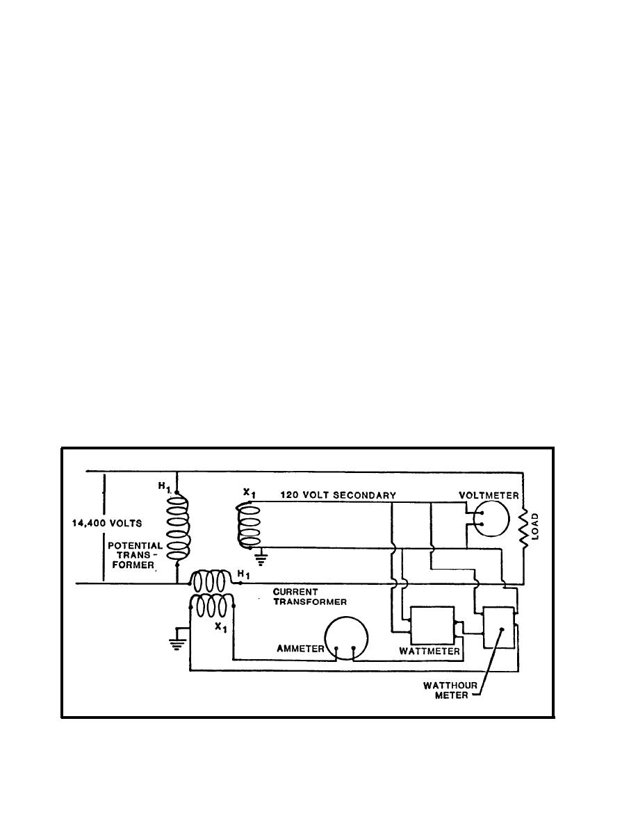
watthour meter may be connected through instrument transformers to a
high-voltage line. It is extremely important that manufacturer's manuals be
followed to ensure a proper meter hookup.
FIGURE 9-14.
Connection of Instrument Transformers
9-27
|
 |
|
|
||


