

Custom Search
|
|

|
||
 WARNING!
If traces of oil or glycol are in the system, and the collectors are hot, a
thick fog of vaporized fluid may come out with the air. It is preferable
to open a vent or valve located outdoors to release the air pressure.
To charge the system, connect up a charging system as shown in Figure 5-27. The
charging pump should be a shallow well jet pump, or a jet pump with a shallow well
adapter capable of developing at least 50 PSI in a deadhead (no flow) situation.
(Figure 5-28) A filter or strainer should be between the bucket and the charging
pump inlet. Change the filter after every five systems.
Following Figure 5-27, one hose will run from the bucket or drum to the inlet of the
charging pump, going through a filter or strainer somewhere along the way. Another
runs from the outlet of the charging pump to the fill port of the fill/drain assembly.
This is the downstream port that the check valve arrow points to. The final hose is
connected to the drain port, and leads back to the bucket.
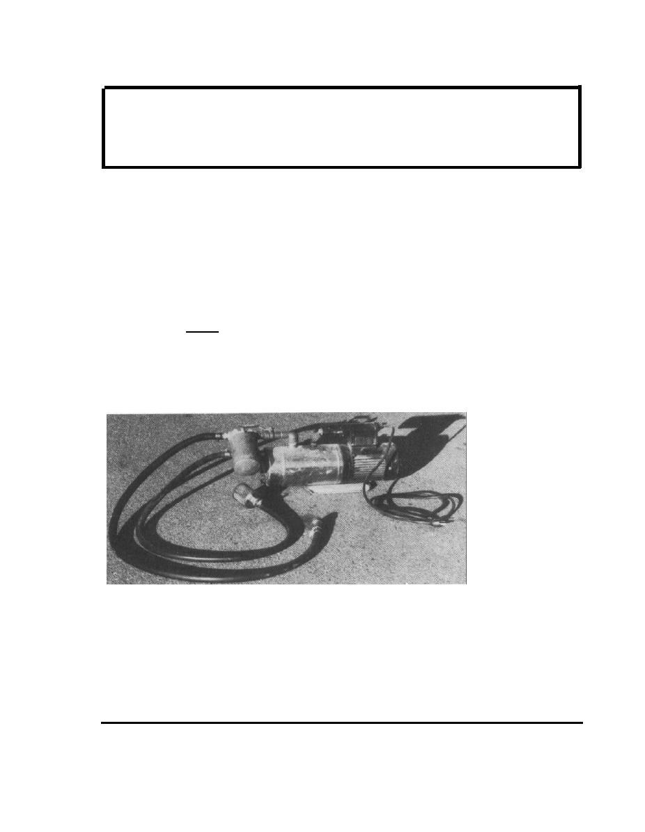
FIGURE 5-28
Typical Charging
Pump
For some systems, especially prepackaged DHW systems, special fittings will be
required for fill/drain assembly connections. (Figure 5-29) For many others, the
fittings end in standard hose threads. Washing machine hoses are useful for
draining and filling.
REPAIR
5.2 REPAIR PROCEDURES
181
|
 |
|
|
||


